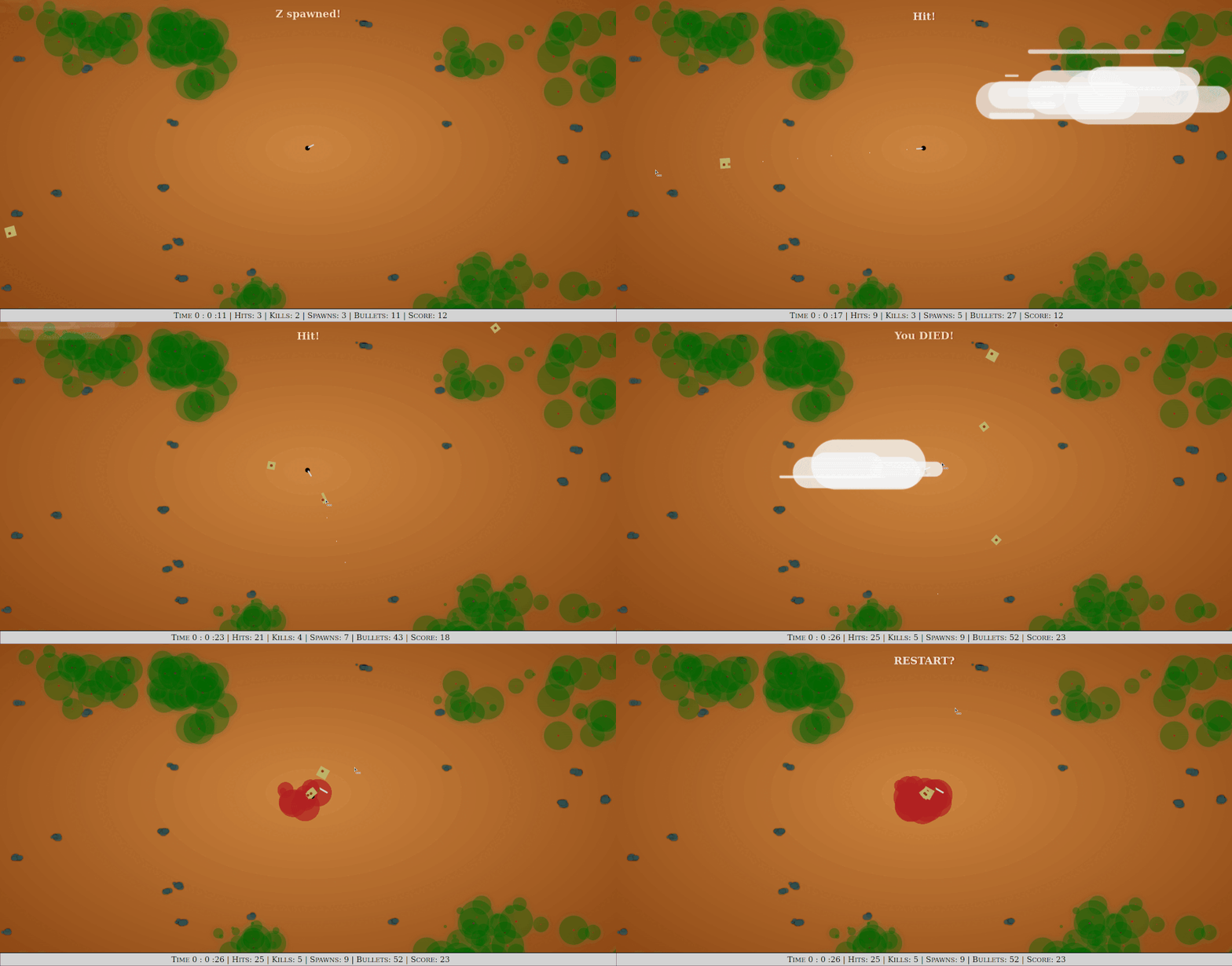
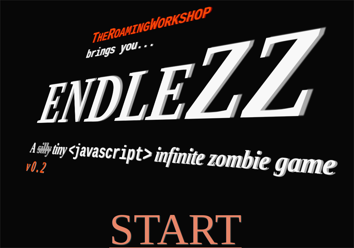
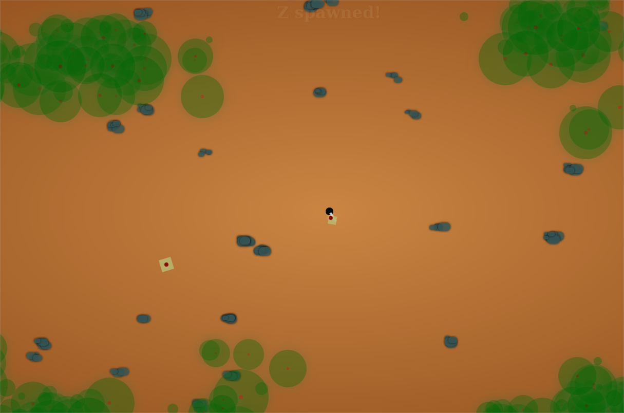
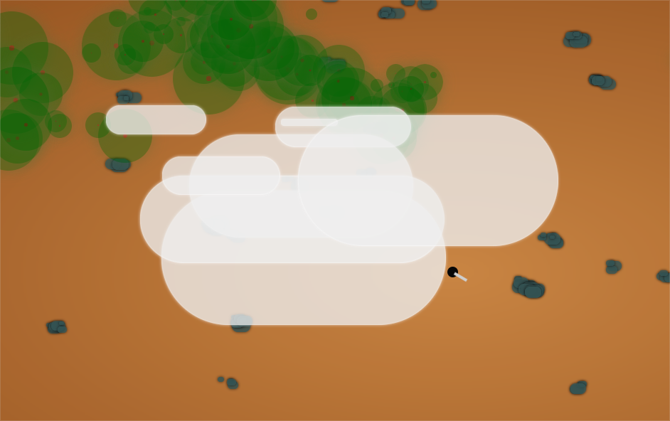
One year ago endleZZ was conceived in a waiting room with no signal as a way to develop an offline game without any special requirements: just a browser and an .html file.
The idea is great and it’s been useful many times to kill some time, but it really deserved a minimum visual and functional update.
So here it is, version 0.2: anniversary update! 🎉
Content
Web version
You can access the web version that I host in this server:
After a few posts about the use of satellite information, let’s see how to bring it (almost) all together in a practical and impacting example. And it’s given the latest wildfires occurred in Spain that they’ve called my attention as I could not imagine how brutal they have been (although nothing compared to the ones in Chile, Australia or USA). But let’s do the exercise without spending too much GB in geographical information.
What I want is to show the extent of the fire occurred in Asturias in March, but also to show the impact removing the trees affected by the flames. Let’s do it!
Content
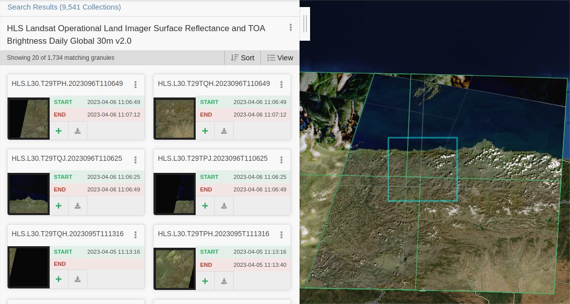
Download data
I will need a Digital Surface Model (which includes trees and structures), an orthophoto taken during the fire, and a Digital Terrain Model (which has been taken away trees and structures) to replace the areas affected by the fire.
1. Terrain models
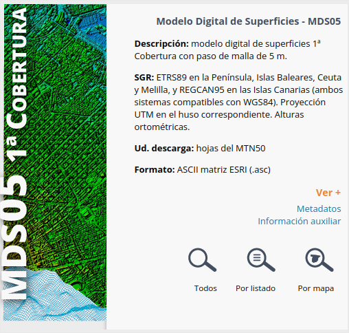
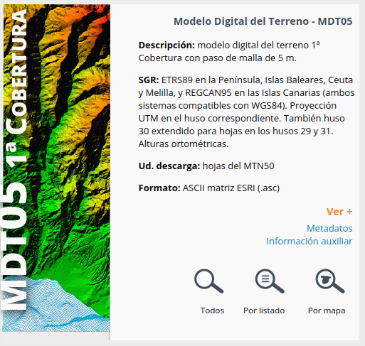
I'm going to use the great models from Spanish IGN, downloading the products MDS5 and MDT5 for the area.
We'll use the process i.group from GRASS in QGIS to group the different bands captured by the satellite in a single RGB raster, as we saw in this previous post:
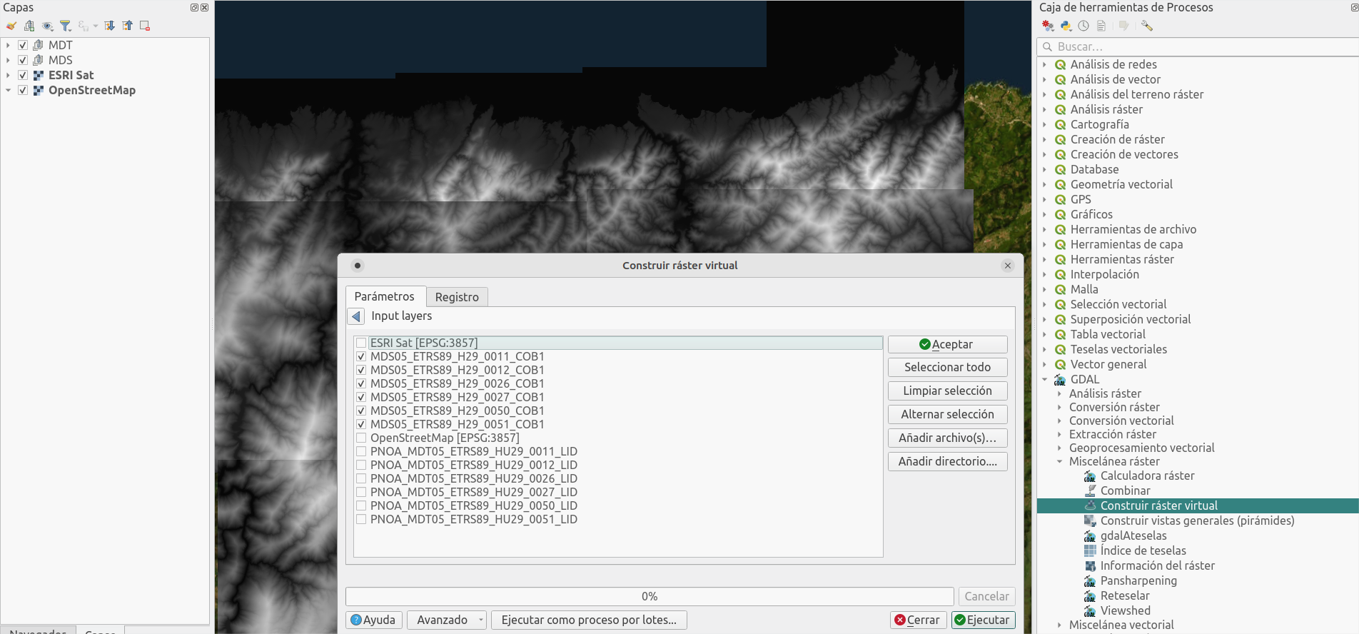
You'll have to do it for every region downloaded, four in my case, that will be joint later using Build virtual raster
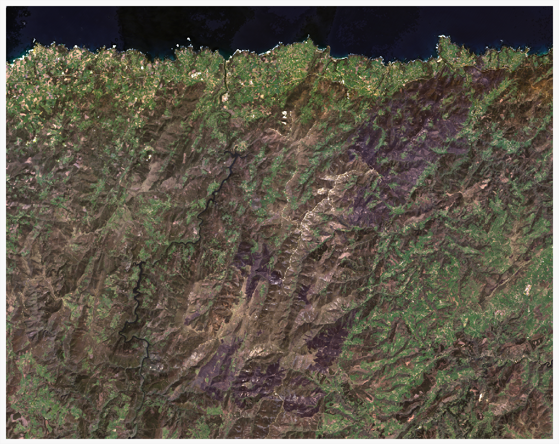
1. True color image (TCI)
Combine bands 4, 3, 2.
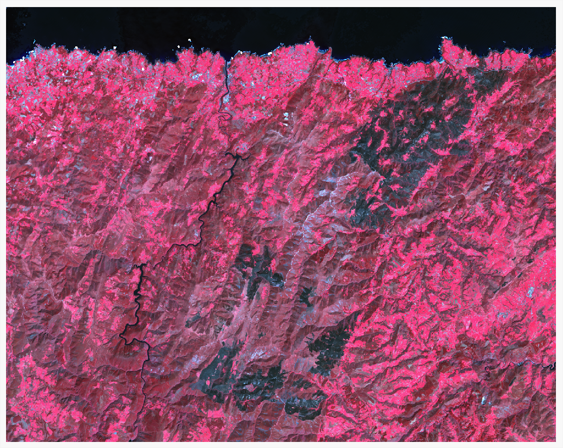
2. False color image
Combine bands 5, 4, 3.
3. Color adjustment
To get a better result, you can adjust the minimum and maximum values considered in each band composing the image. These values are found in the Histogram inside the layer properties.
here you have the values I used for the pictures above::
Band
TCI min
TCI max
FC min
FC max
1 Red
-100
1500
-50
4000
2 Green
0
1500
-100
2000
3 Blue
-10
1200
0
1200
Fire extent
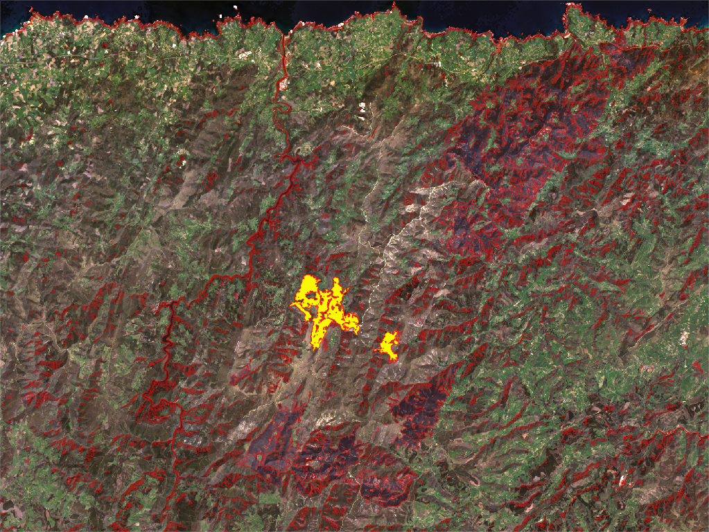
As you can see, the false color image shows a clear extension of the fire. We'll generate a polygon covering the extent of the fire with it.
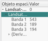
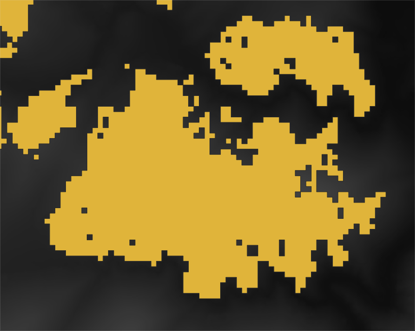
First, let's query the values in Band 1 (red) which offers a good contrast for values in the area of the fire. They are in the range 300-1300.
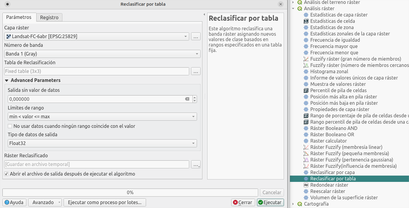
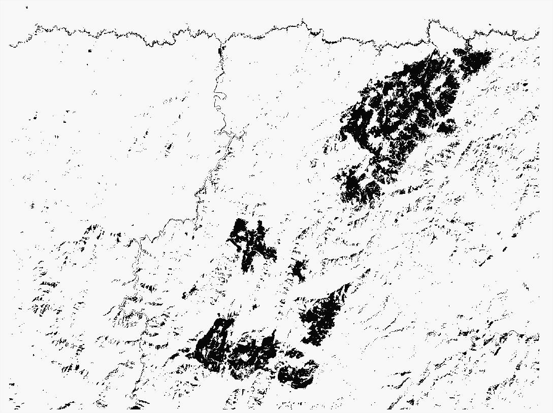
Using the process Reclassify by table, we'll assign value 1 to the cells inside this range, and value 0 to the rest.
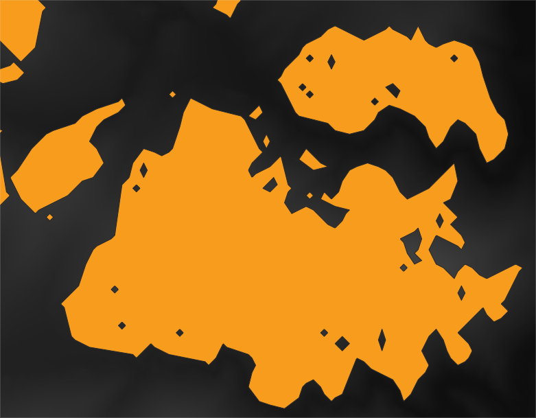
Vectorize the result with process Poligonize and, following the satellite imagery, select those polygons in the fire area.
Use the tool Dissolve to merge all the polygons in one element; then Smooth to round the corners slightly.
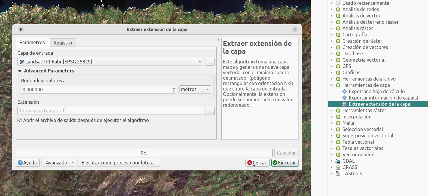
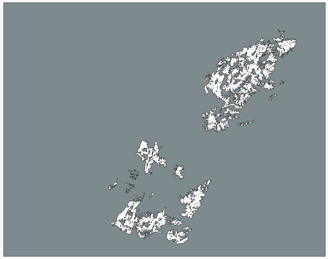
Let's now get the inverse. Extract by extent using the Landsat layer, then use Difference with the fire polygon.
Process terrain
1. Combine terrain data
Join the same type model files in one (one for the DSM, and another one for the DTM). Use process Build virtual raster
2. Extract terrain data
Extract the data of interest in each model:
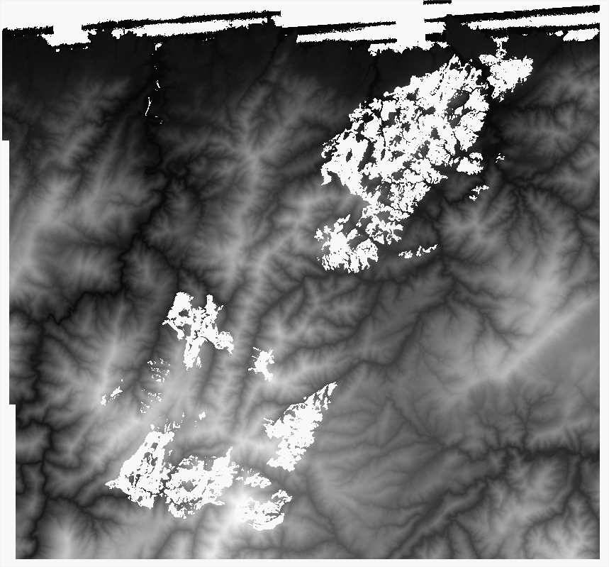
From the DSM extract the surface affected by the fire, so you'll remove all the surface in it.
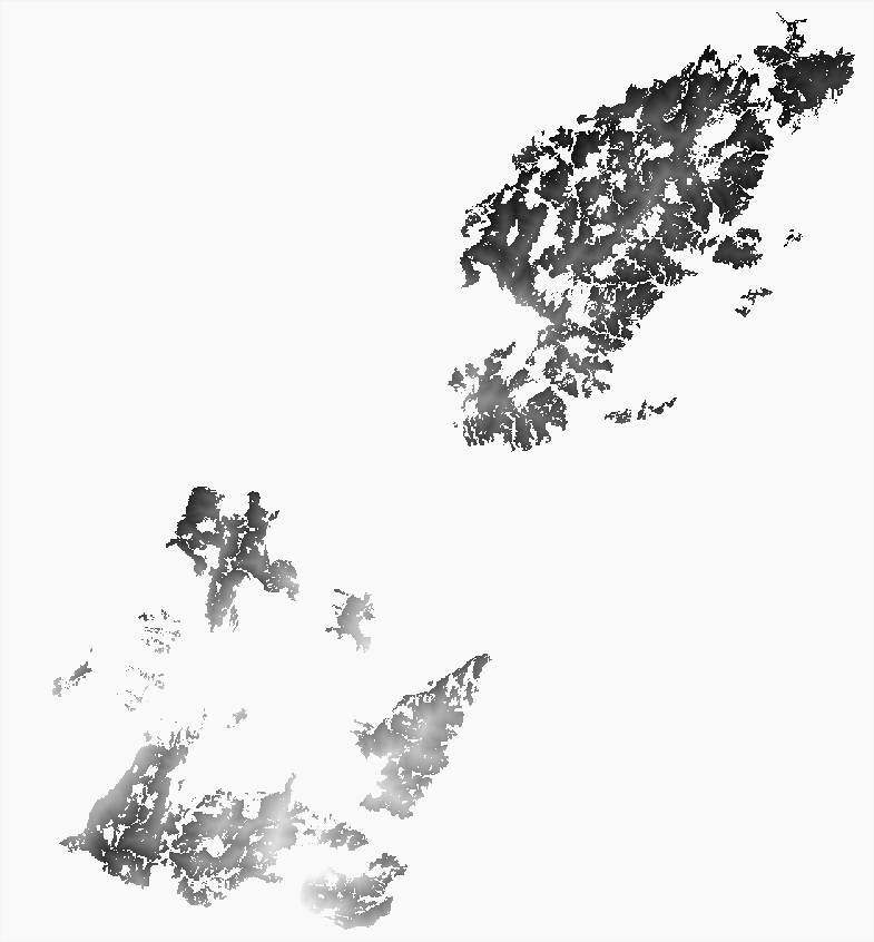
Do the opposite with the DTM: keep the terrain (without trees) in the fire area, so it will fill the gaps in the other model.
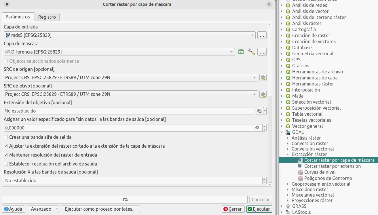
Use the process Crop raster by mask layer using the layers generated previously.
Finally join both raster layers, so they fill each others' gaps, using Build virtual raster.
Bring it to life with Cesium JS
You should already have a surface model without trees in the fire area, but let's try to explore it in an interactive way.
I showed a similar example, using a custom Digital Terrain Model, as well as a recent satellite image, for the Tajogaite volcano in La Palma:
In this case I'll use Cesium JS again to interact easily with the map (follow the post linked above to see how to upload your custom files to the Cesium JS viewer).
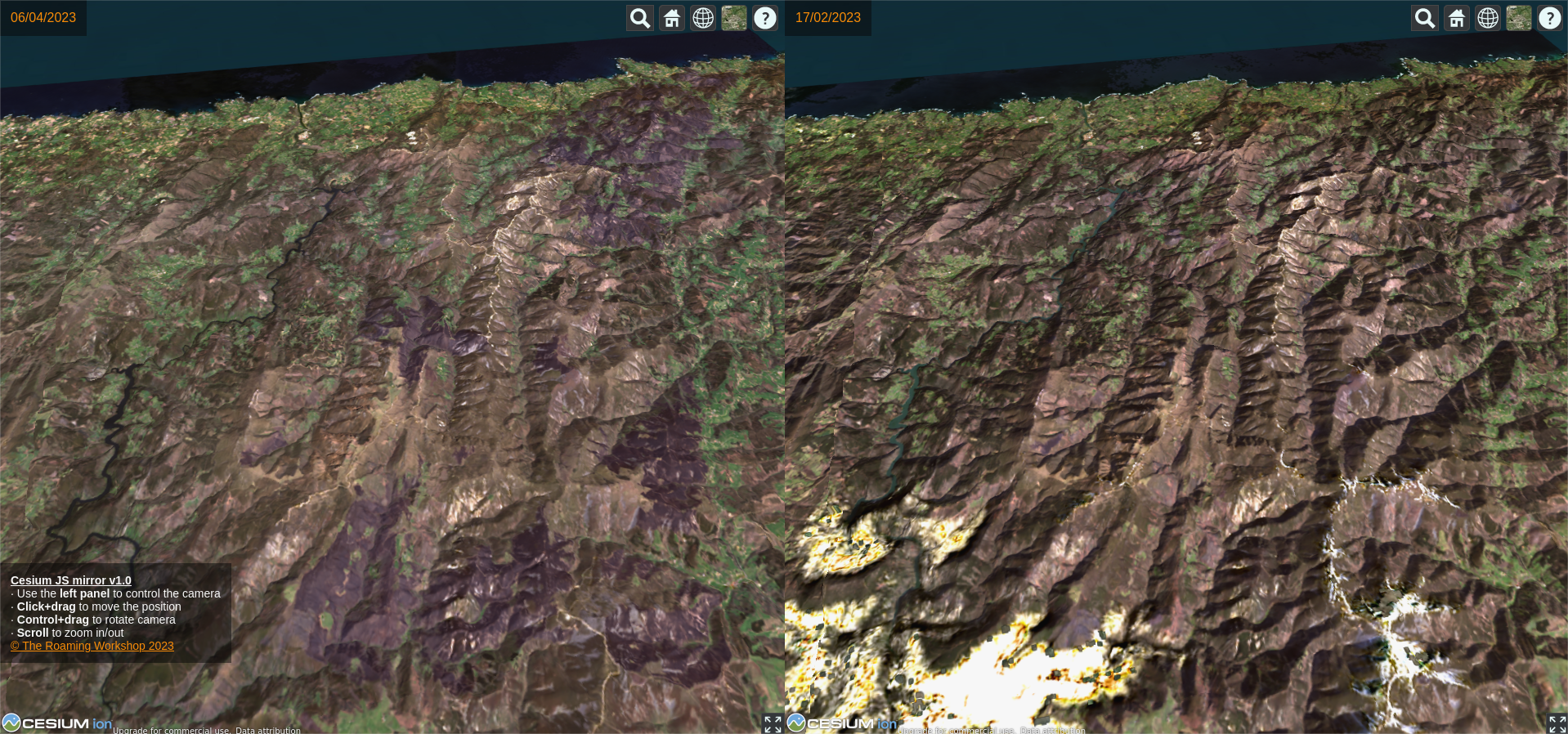
For this purpose, I created a split-screen viewer (using two separate instances of Cesium JS) to show the before and after picture of the fire. Here you have a preview:
I hope you liked it! here you have the full code and a link to github, where you can download it directly. And remember, share your doubts or comments on twitter!
Sometimes a Digital Terrain Model (DTM) might not be detailed enough or poorly cleaned. If you have access to LIDAR data, you can generate a terrain model yourself and make the most of the raw information giving more detail to areas of interest. Let’s see how.
Content
1. Data download
Point cloud
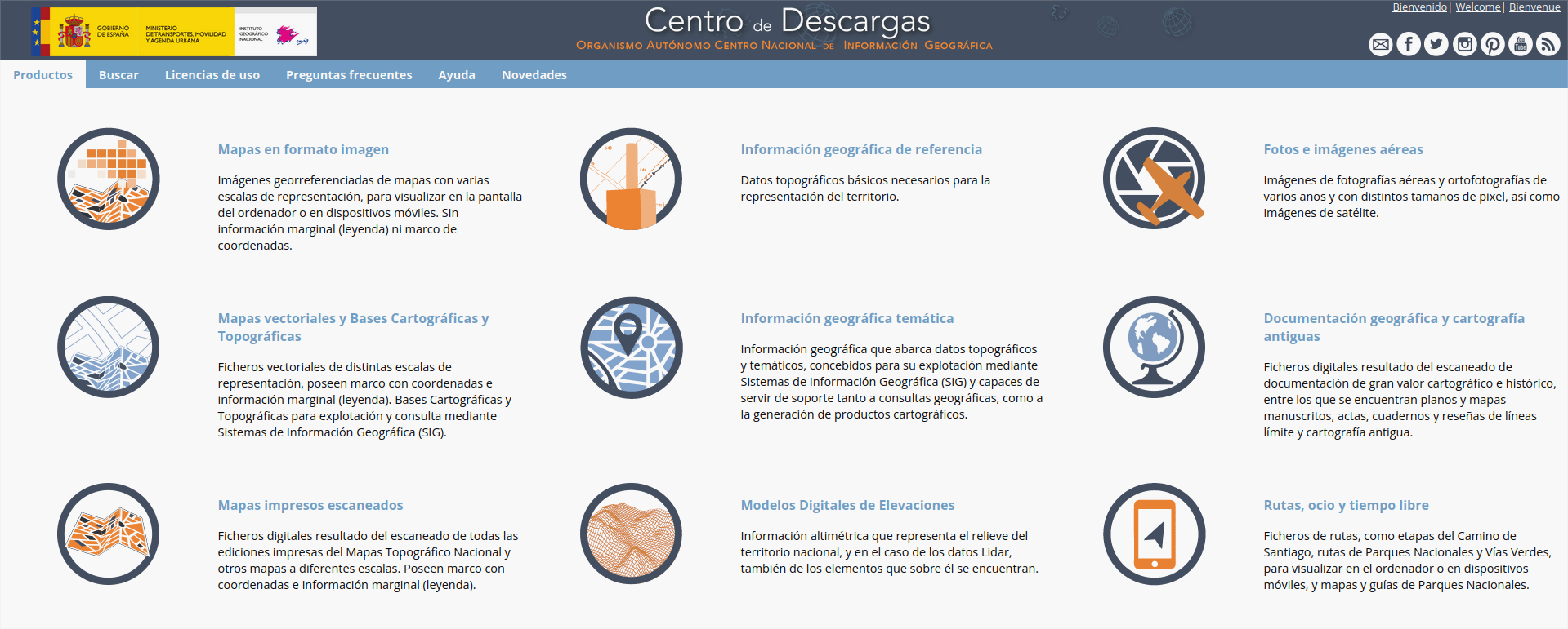
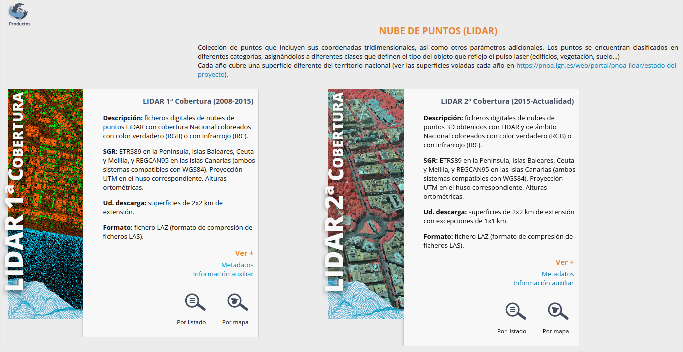
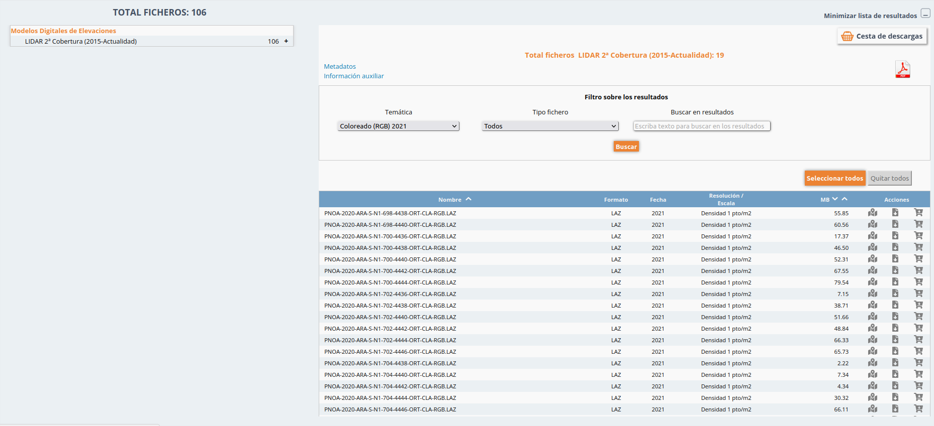
I'll use the awesome public data from the Spanish Geographical Institute (IGN) obtained with survey flights using laser measurements (LIDAR).
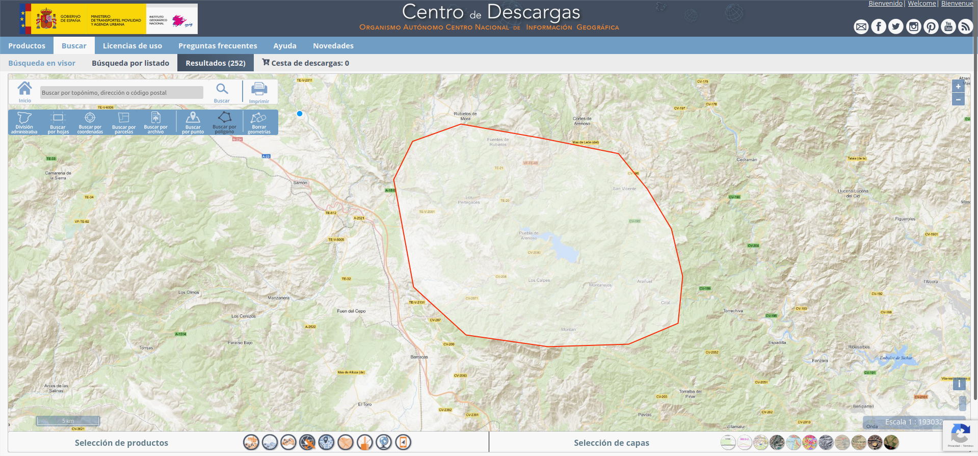
Download the files PNOA-XXXX...XXXX-RGB.LAZ. RGB uses true color; ICR, infra-red. But both are valid.
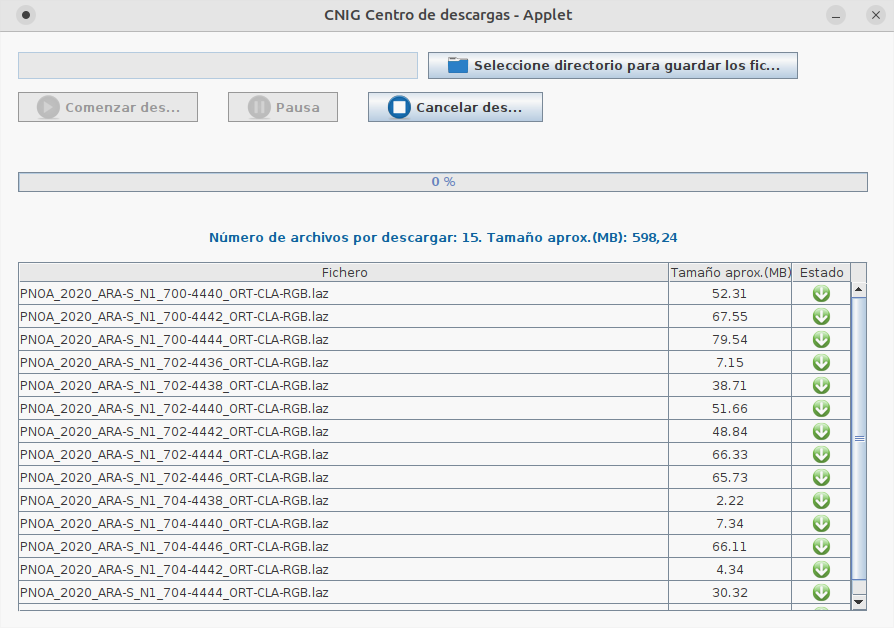
TIP! Download all files using the IGN applet. It's a .jnlp file that requires Java instaled on Windows or IcedTea on Linux (sudo apt-get install icedtea-netx)
2. Process LIDAR point cloud in QGIS
Direct visualization
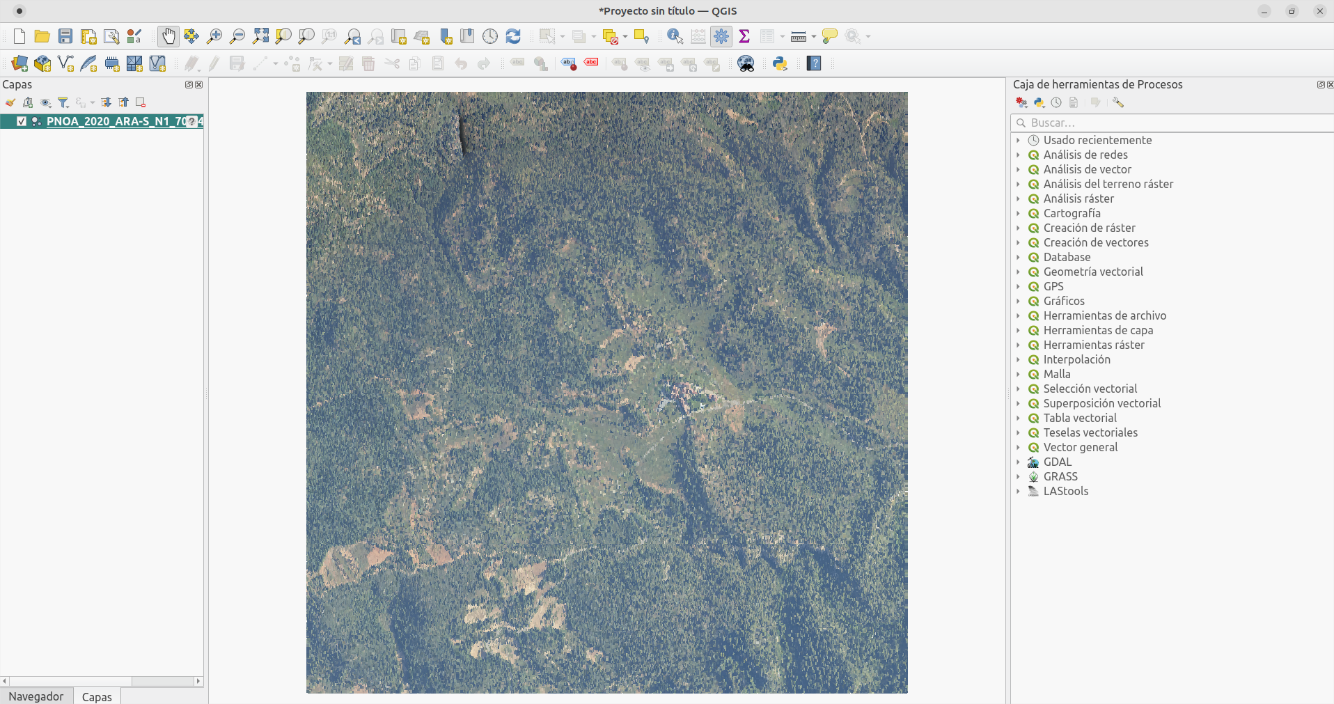
From the latest versions (like 3.28 LTR Firenze), QGIS includes compatibility with point cloud files.
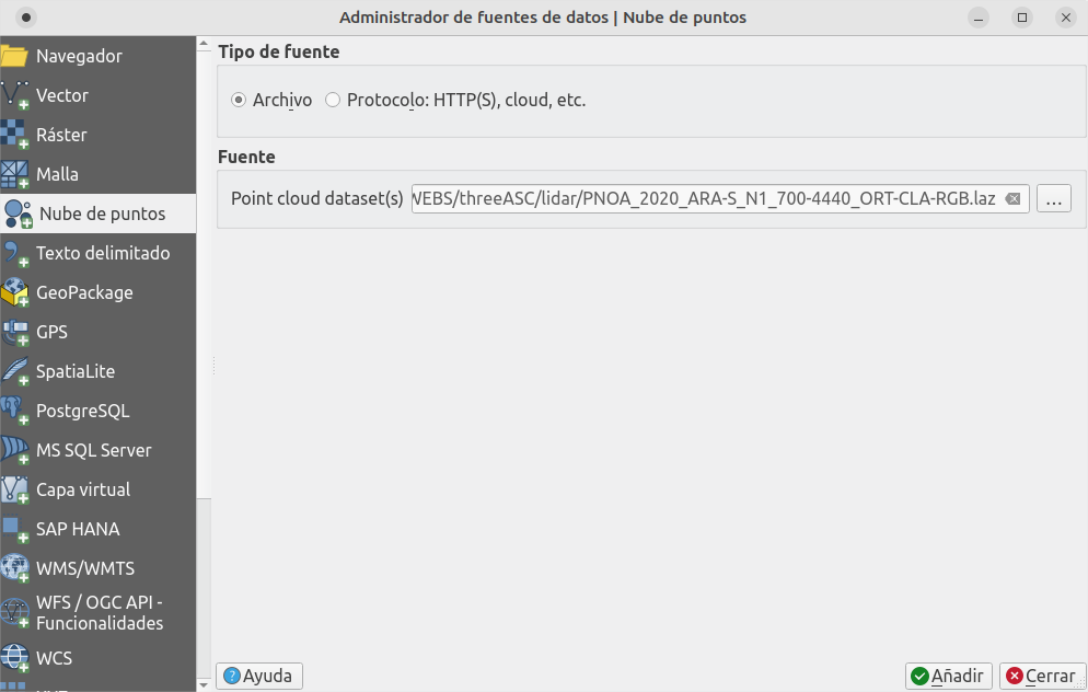
Just drag and drop the file to the canvas or, in the menu, Layer -> Add layer... -> Add point cloud layer...
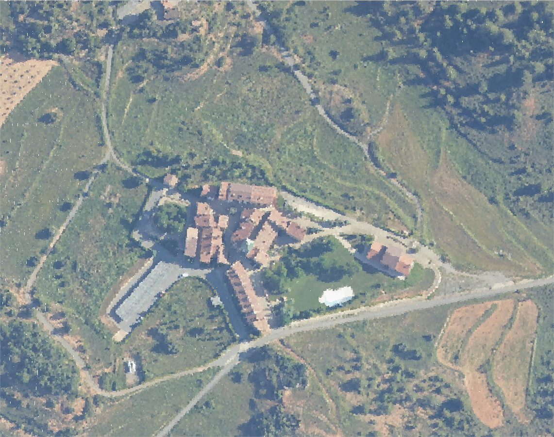
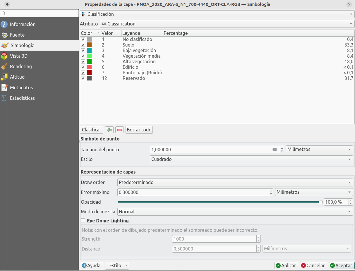
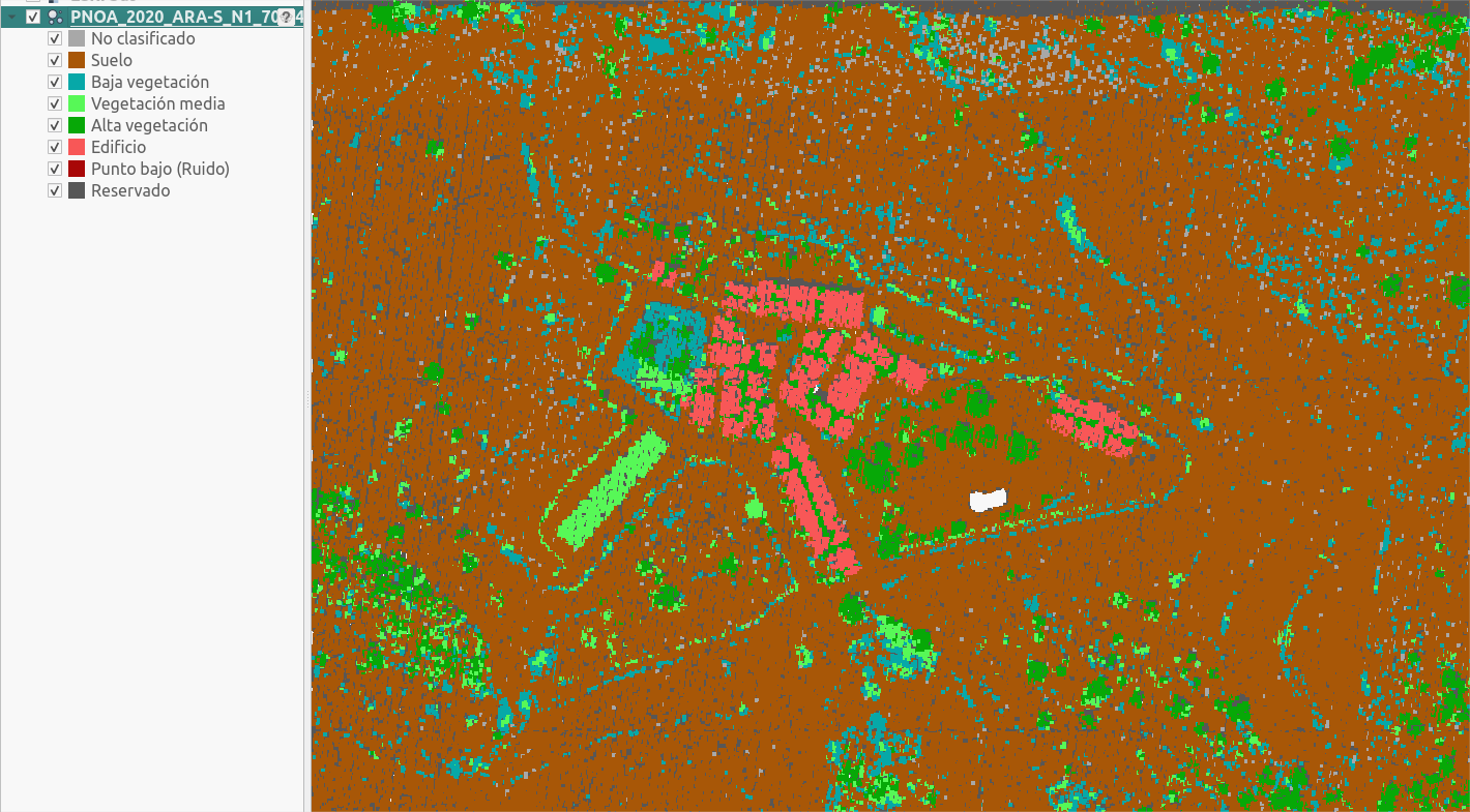
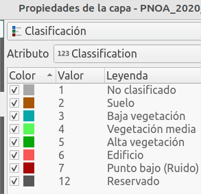
You'll see the true color data downloaded, which you can classify in the SimbologyProperties, choosing Clasification by data type:
3D view
Another default function coming with QGIS is 3D visualization of the information.
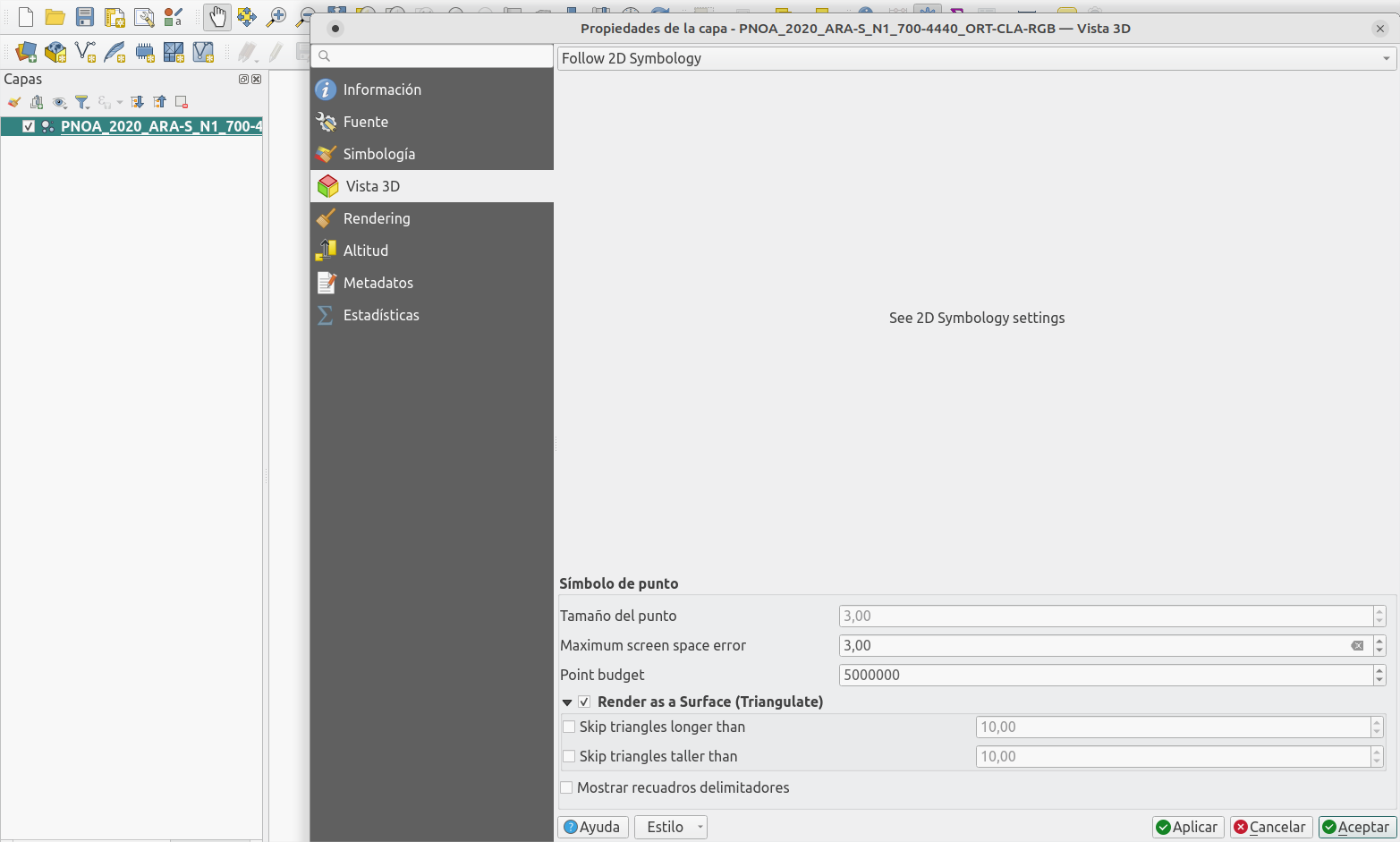
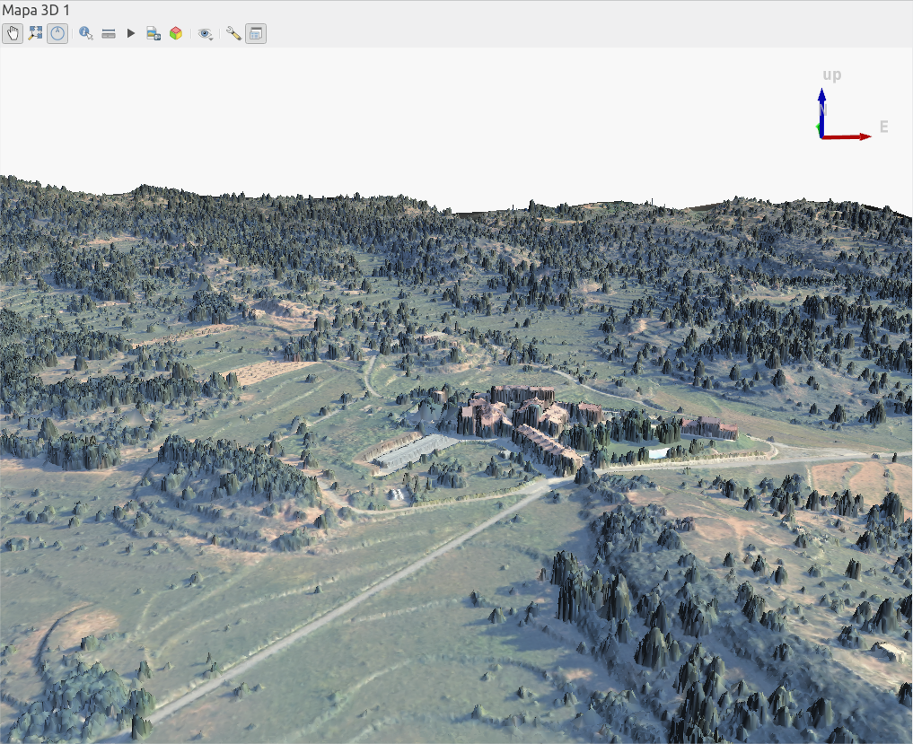
Let's configure the 3D properties of the LIDAR layer to triangulate the surface and get a better result.
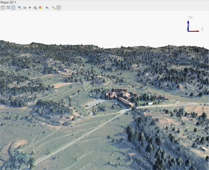
Now, create a new view in the menu View -> 3D Map Views -> New 3D map view. Using SHIFT+Drag you can rotate your perspective.
LAStools plugin
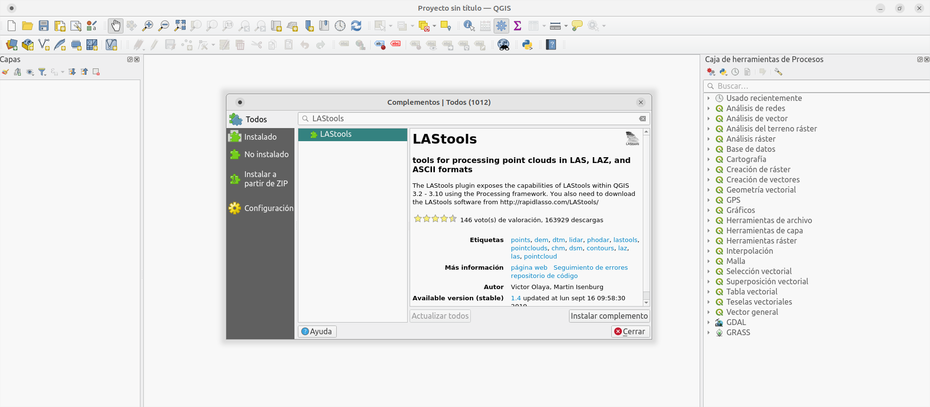
To handle LIDAR information easily we'll use the tools from a plugin called LAStools, which you can install in the following way:
TIP! On Linux it's recommended to install Wine to use the .exe files directly, or otherwise you'll need to compile the binaries.
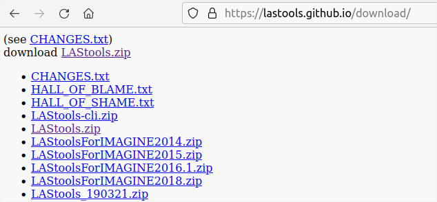
Access LAStools' website and scroll to the bottom:
The full tool comes to a price, but you can access the public download to use the basic functions that we need.
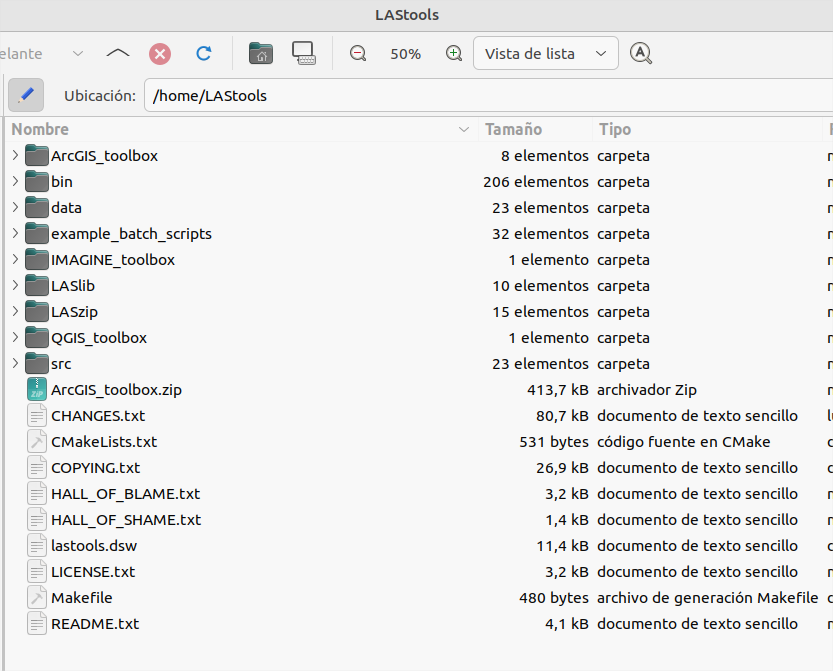
Unzip the compressed .zip file in a simple folder (without spaces or special characters)
Now open QGIS, search in the plugins list for LAStools and install it.
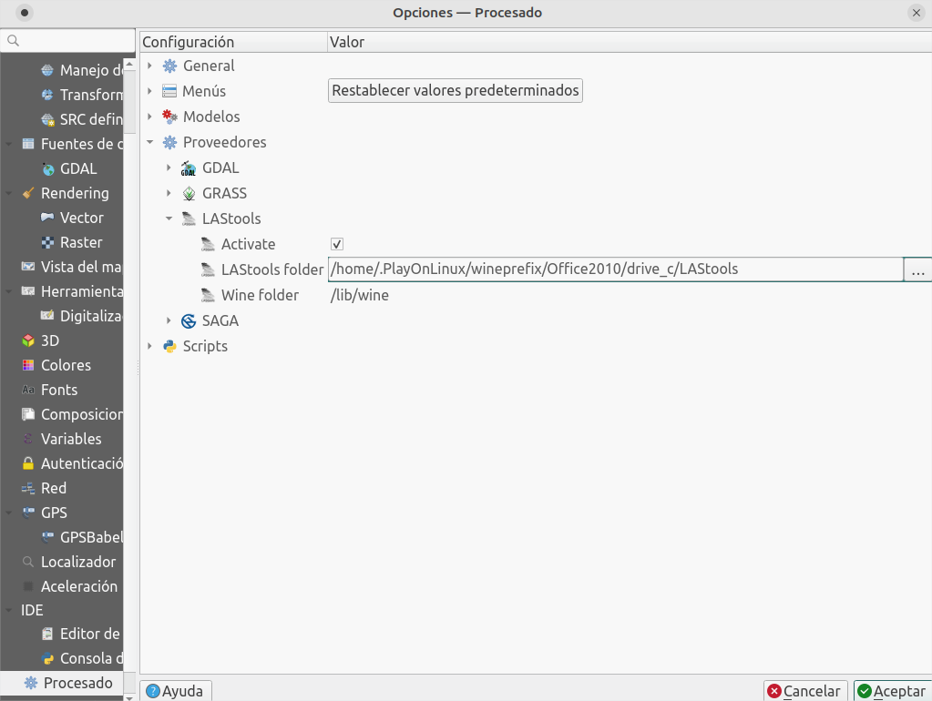
Finally, configure LAStools' installation folder (if it's different from the default C:/ ). The settings shown below work in Linux with Wine installed (using PlayOnLinux in my case).
Extract types of LIDAR data
Using LAStools we can extract information of the different data that makes up the point cloud. For example, we'll only extract the data classified as Suelo (soil) which is assigned to a value of 2.
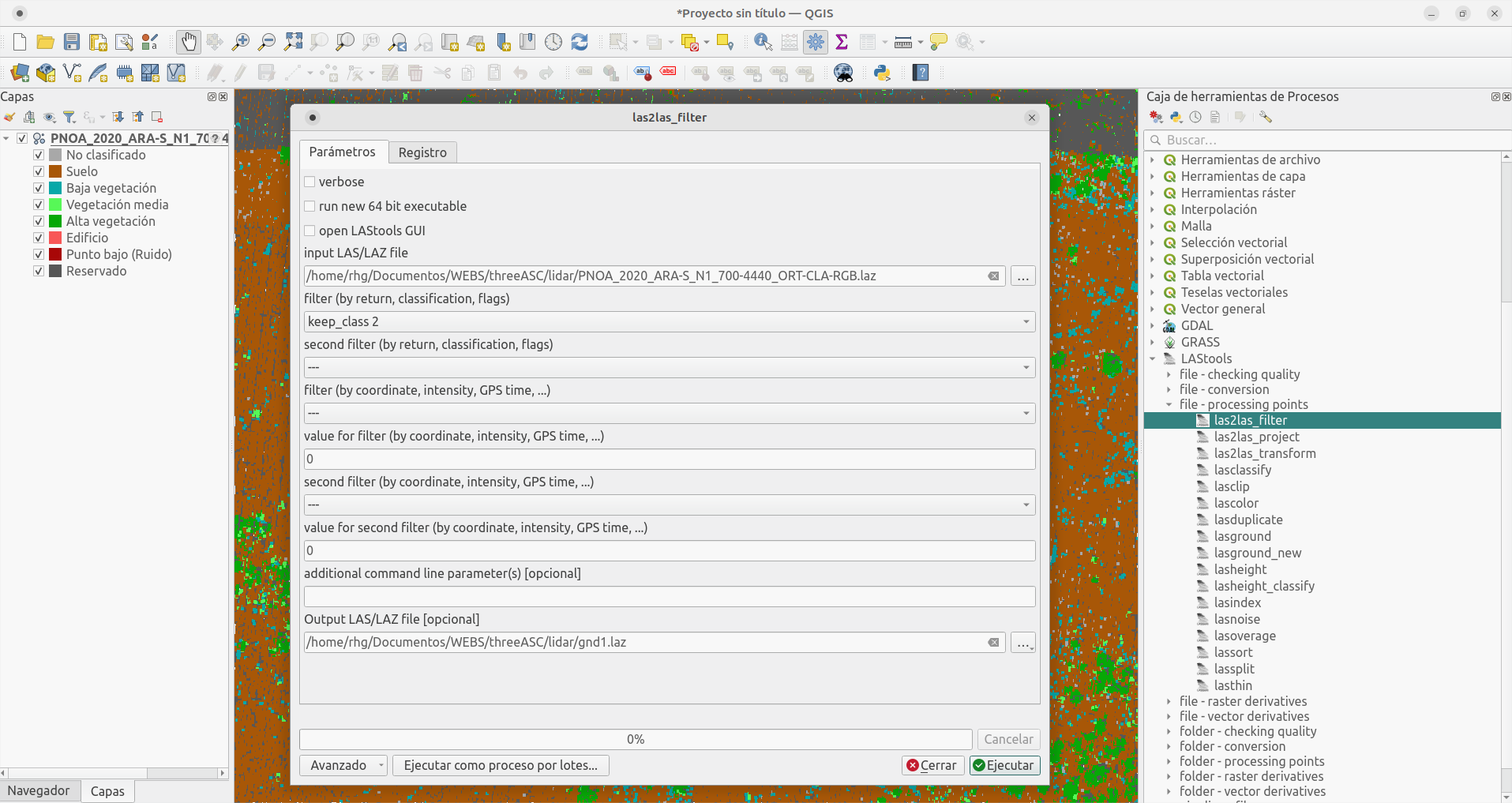
With the process las2las_filter we'll create a filtered point cloud:
Select the .laz file to filter.
On filter, choose the option to keep_class 2
Leave the rest by default, and introduce 0 where the fields require a value
Finally, save the file with .laz extension in a known location to find it easily.
Once finished, just load the generated file and see the point cloud showing only ground data (with buildings and vegetation removed).
LIDAR to vector conversion
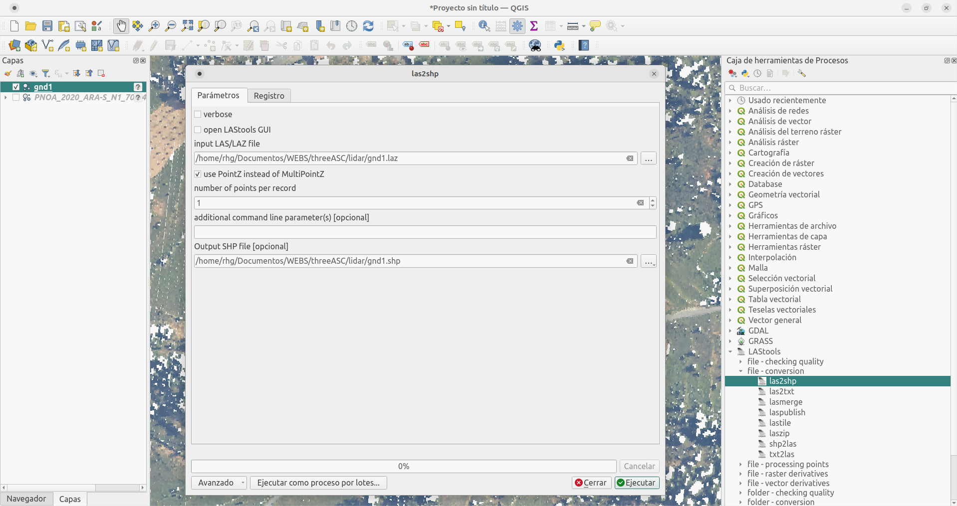
Now use the process las2shp to transform the point cloud into a vector format so you can operate easily with other GIS tools:
Choose the point cloud file just filtered.
Specify 1 point per record to extract every point of the cloud.
Save the file with .shp extension in a known location to find it easily.
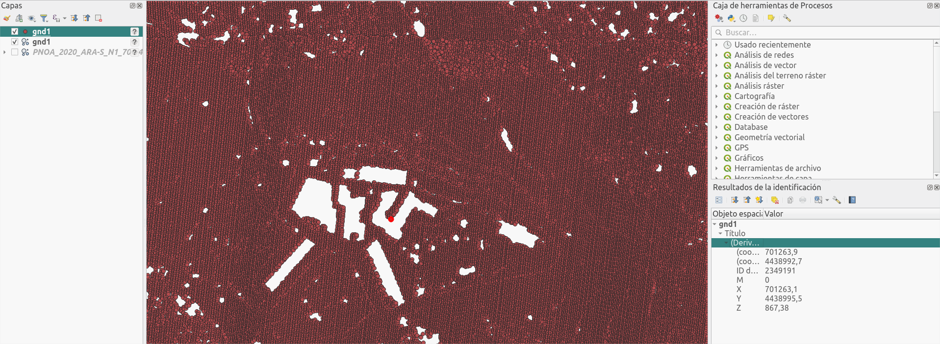
And this will be your filtered point cloud in the classic vector format.
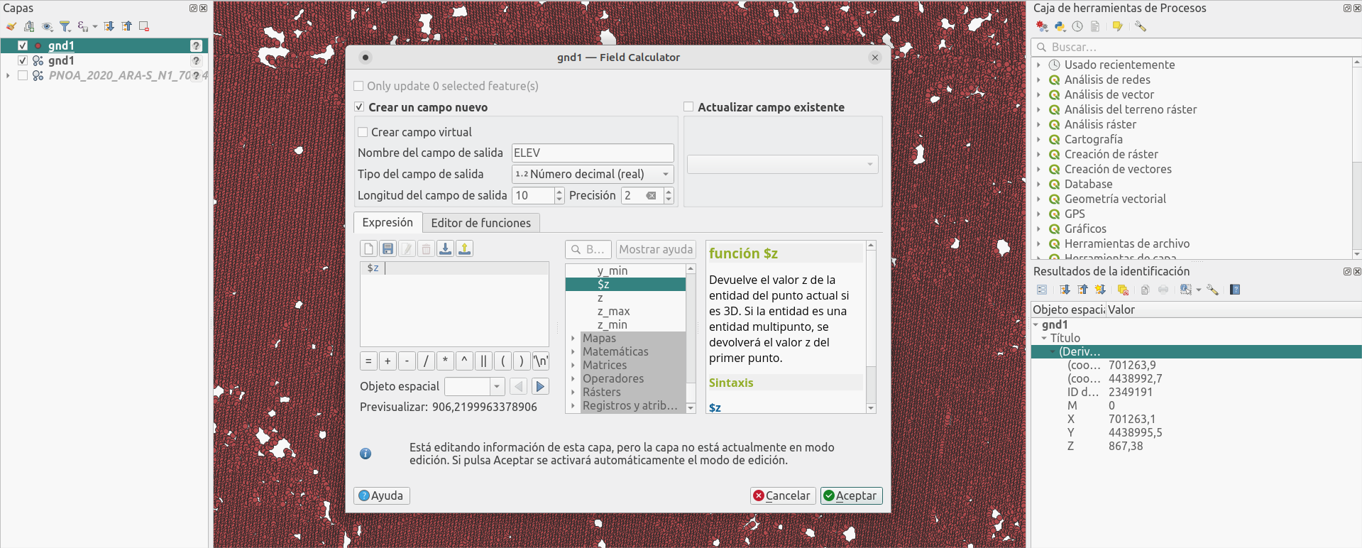
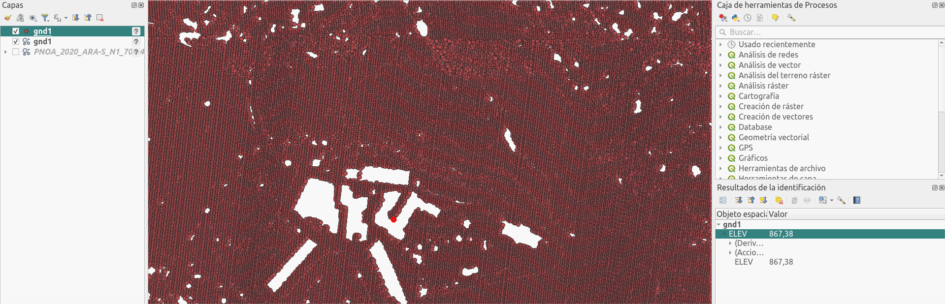
You can see that there is no specific field in the table of attributes. I'll create a new field ELEV to save the Z (height) coordinate and use it to generate a Digital Terrain Model.
3. Digital Terrain Model creation
Raster form vector point layer
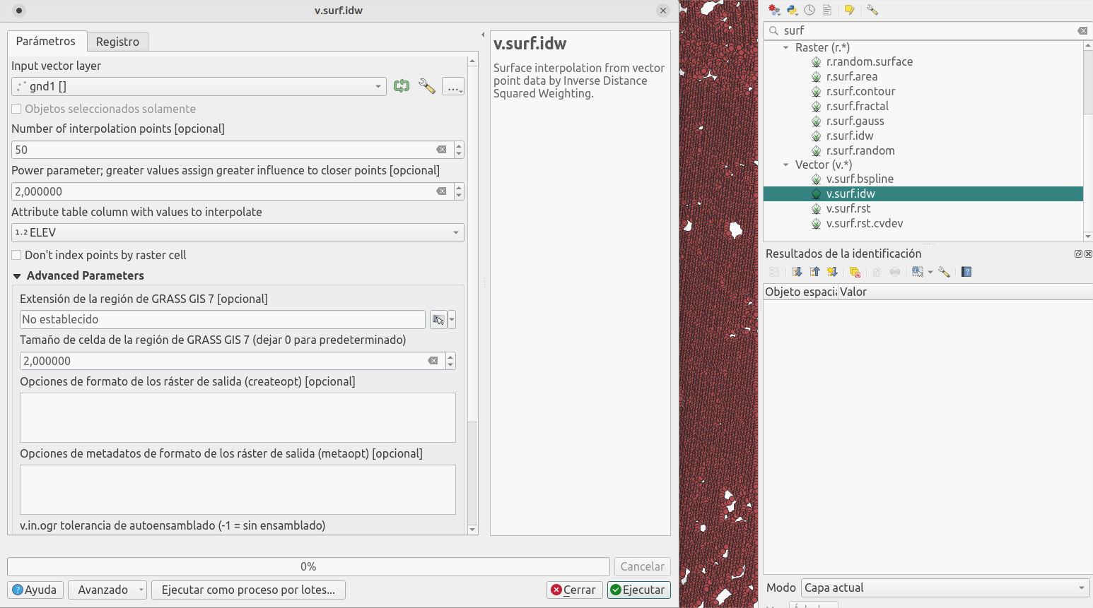
Thanks to the integration of GRASS GIS, we can make use of powerful vector and raster processing tools. Let's use v.surf.idw to generate a regular grid from the interpolation of data in a point layer (in this case the values are weighted with the inverse of the distance but the are other spline algorithms).
Choose the vector point layer.
Choose the number of points to use for interpolation (in this case the data is quite dense so I'll choose 50). The more you choose, the softer the result will be, at the expense of losing the detail of the information density.
Leave the power with the value of 2, to use "square inverse distance".
Choose the data field used in the interpolation (ELEV).
Define the grid cell size. I choose 2 to compare the result with the 2m DTM product from IGN.
4. Result
Let's zoom out and see how it all finished:
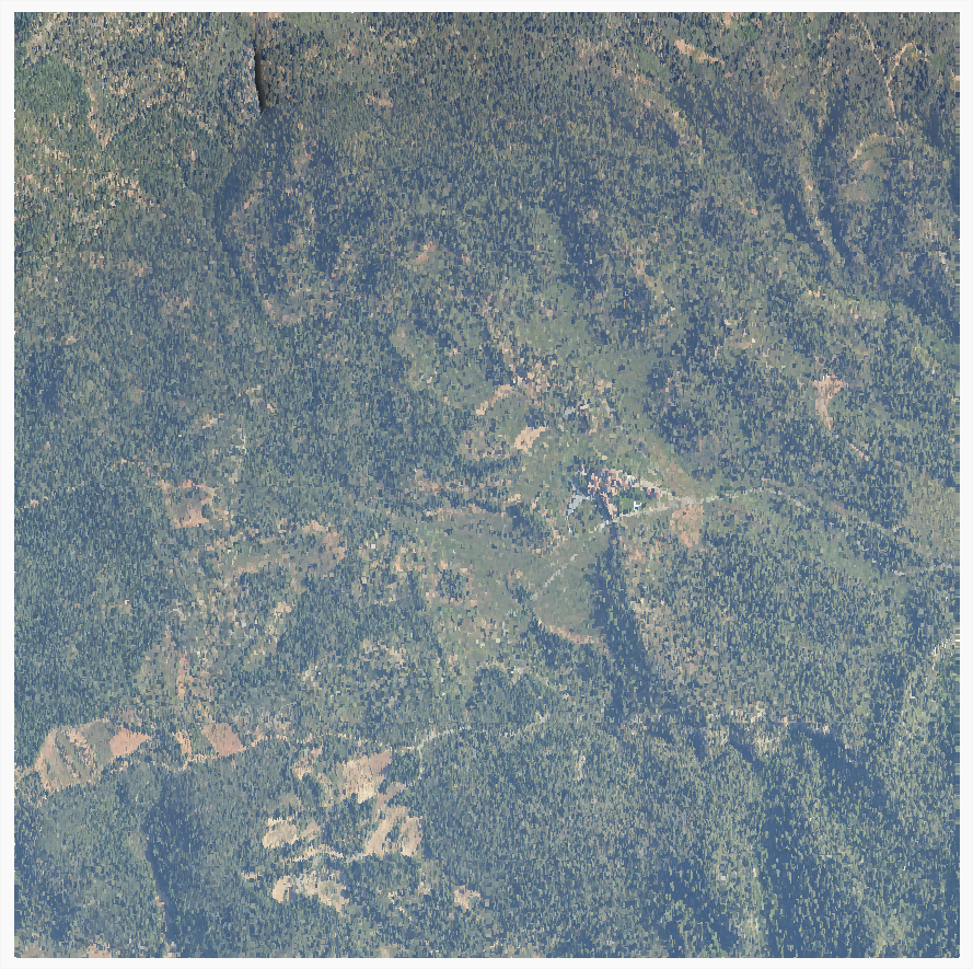
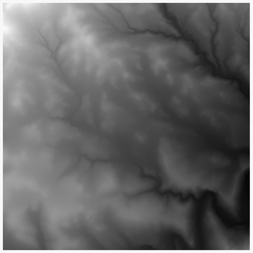
RGB LIDAR point cloud2 meter DTM from LIDAR
And now let's see a bit more detail.
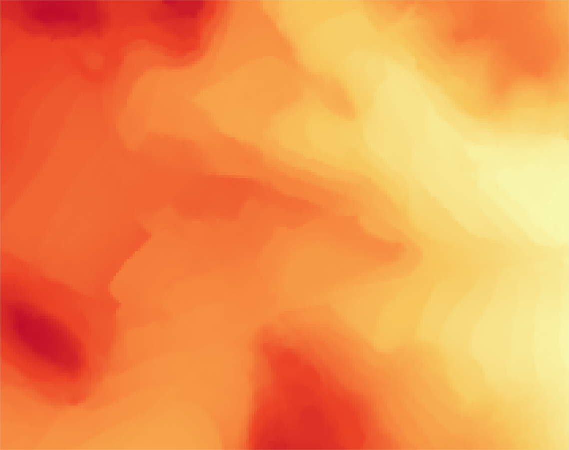
Apply the same color ramp to the generated DTM and to the IGN product. Overall, the result is very similar, with some differences in tree areas, being more reasonable in the processed layer.
MDT 2m LIDARMDT 2m IGNLIDAR + SatIGN + Sat
And that's it! Any doubt or comment can be dropped on Twitter!
AI trends are here to stay, and today there’s much talk about Vall-E and its future combination with GPT-3. But we must remember that all these Artificial Intelligence products come from collaborative investigation that have been freely available, so we will always find an open-source equivalent, and we must be thankful about it.
That’s the case of TorToiSe-TTS (text to speech), an AI voice generator from written text totally free to use in your PC.
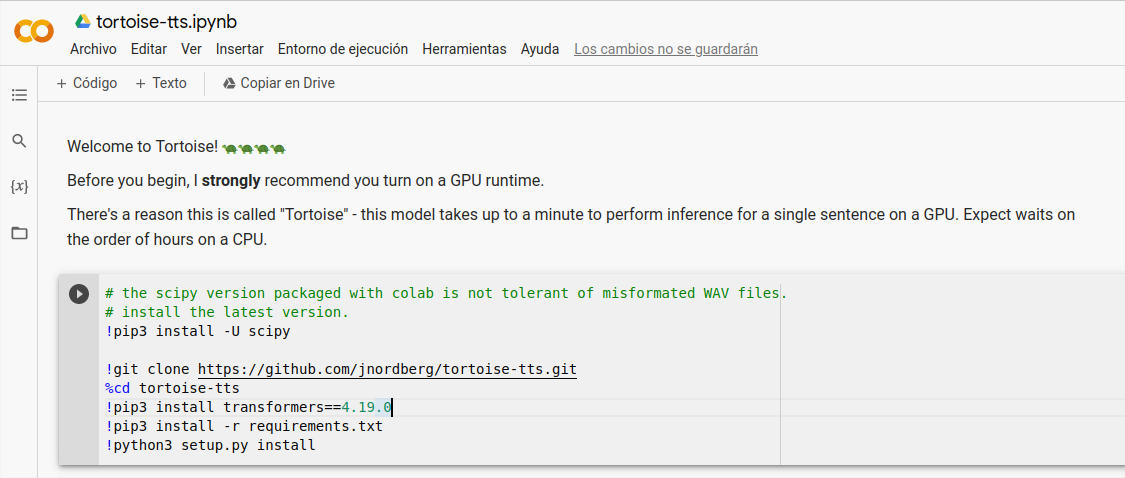
You just need to sign in and click "play" ▶ to run each block of code.
But for sure you want to run TorToiSe-TTS locally, without internet, and save the audio in your local drive, so let's move on.
Installing python3
Like many AI applications, TorToiSe-TTS runs in python, so you need python3 in your PC. I always recommend the use of Linux, but you might be able to run it in a Windows terminal as well.
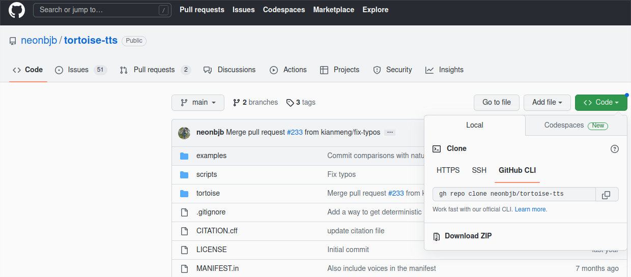
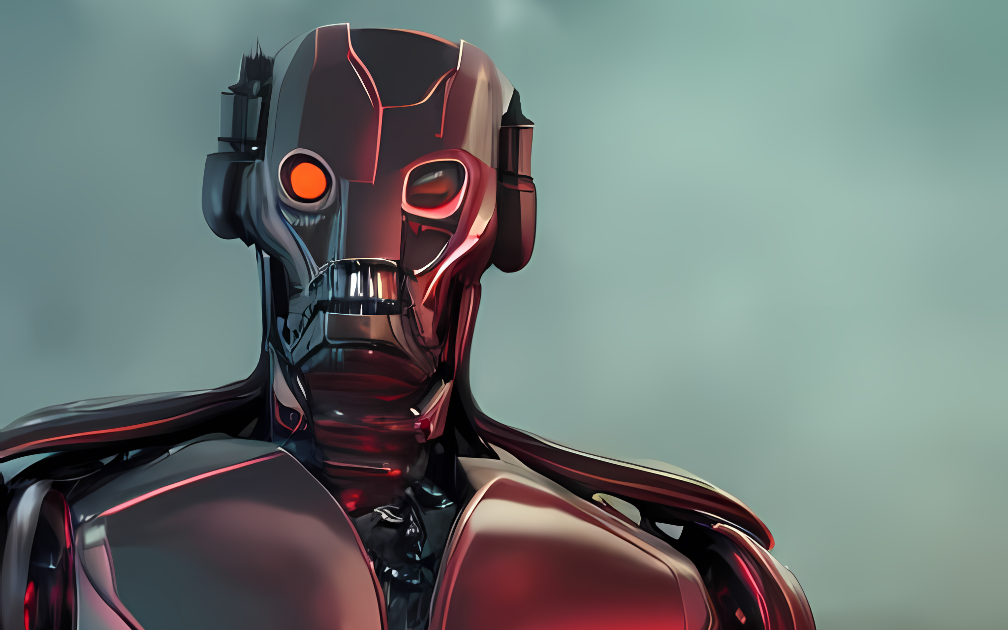
You can also download my fork repository, where I add further installation instructions, a terminal automatic launcher and some test voices for Ultron (yes, Tony Stark's evil droid) which we'll see later on.
Next we'll have to install a series of python modules needed to run TorToiSe-TTS, but before this, we'll create a virtual python version, so the installation of these modules won't affect the rest of the python installation. You'll find this helpful when you use different AI apps that use different versions of the same module.
Open a terminal and write the following, so you'll create a "TTS" environment:
cd tortoise-tts
python3 -m venv TTS
Activate it this way:
source TTS/bin/activate
And now you'll see a referente to the TTS environment in the terminal:
(TTS) abc@123:~$ |
Install python modules
Let's now install the required modules, following the collab indications:
"text": text chain that will be converted to audio
-v: voice to be used to convert text. It must be the name of one of the folders available in /tortoise/voices/
-V: specifies a folder for voices, in the case that you use a custom one.
--seed: seed number to feature the algorithm (can be any number)
-p: preset mode that determines quality ("ultra_fast", "fast", "standard", "high_quality").
-o: route and name of the output file. You must specify the fileformat, which is .wav
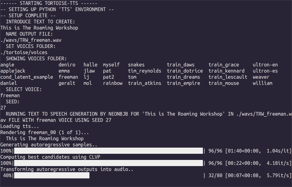
If you use my repo script TTS.sh you'll be asked for these arguments on screen and it will run the algorithm automatically.
Add your own voices
You can add more voices to TorToiSe-TTS. For example, I wanted to add the voice of Ultron, the Marvel supervillain, following the developer Neonbjb indications:
You must record 3 "clean" samples (without background noise or music) of about 10 seconds duration.
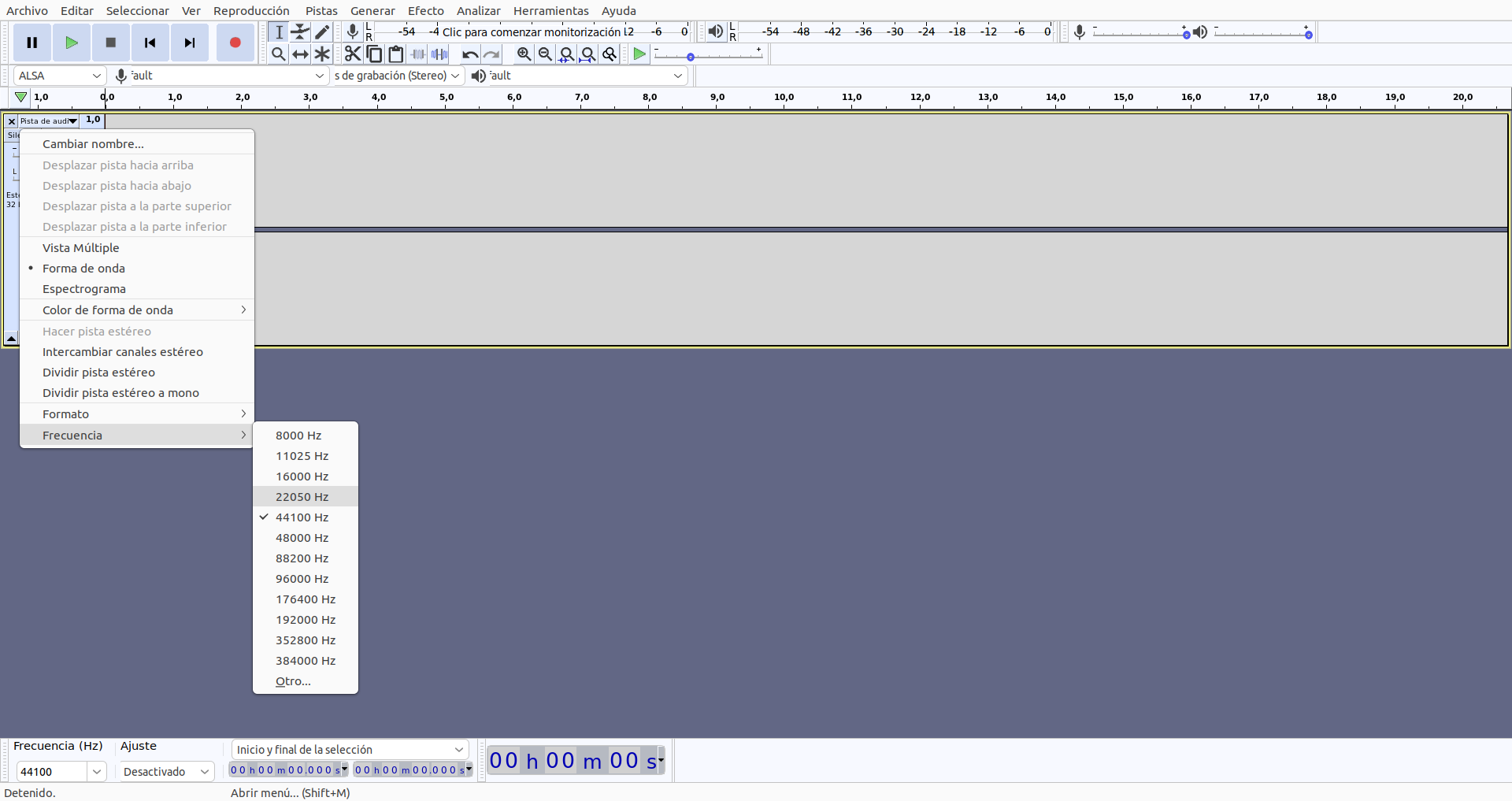
The format must be 16bits floating point WAV with 22500 sample rate (you can use Audacity)
Create a new folder inside /tortoise/voices (or anywhere, really) and save your recordings there.
When running TorToiSe-TTS, you'll need to call the voices folder with argument -V and the new voice with argument -v
For example, to use my Ultron recordings:
python3 sripts/tortoise_tts.py "This is The Roaming Workshop" -V "./tortoise/voices" -v "ultron-en" -p "fast" --seed 17 -o "./wavs/TRW_ultron3.wav"
Which sound like this:
I've taken cuts from a scene in Avengers: age of Ultron, both in English (ultron-en) and Spanish (ultron-es) which you can download from my repository.
"Ultron supervillain" by Optimised Stable Diffusion + Upscayl 2. The Roaming Workshop 2023.
Right now, the TorToiSe-TTS model is trained only in English, so it only woks properly in this language.
You can introduce text in another language, and AI will try to read it, but it will use the pronunciation learnt in English and it will sound weird.
If you are willing to train a model in your language (you need plenty GPU and several months), contact the developer, as he's keep to expand the project.
In the meantime, you can send any doubts or comments on 🐦 Twitter or 🐤 Koo!
AI image generation has a high computational cost. Don’t trust the speed of Dall·E 2 API that we saw in this post; if these services are usually paid, it’s for a reason and, apart from the online services that we also saw, running AI in an average computer is not so simple.
After trying, in vane, some open-source alternatives like Pixray or Dalle-Flow, I finally bring the most simple of them: dalle-playground. This is a starting version of Dalle, so you won’t obtain the best of the results.
Despite this, I will soon bring an alternative to Dall·E (Stable Diffusion from stability.ai), which also supports a version optimized by the community for low resources PCs.
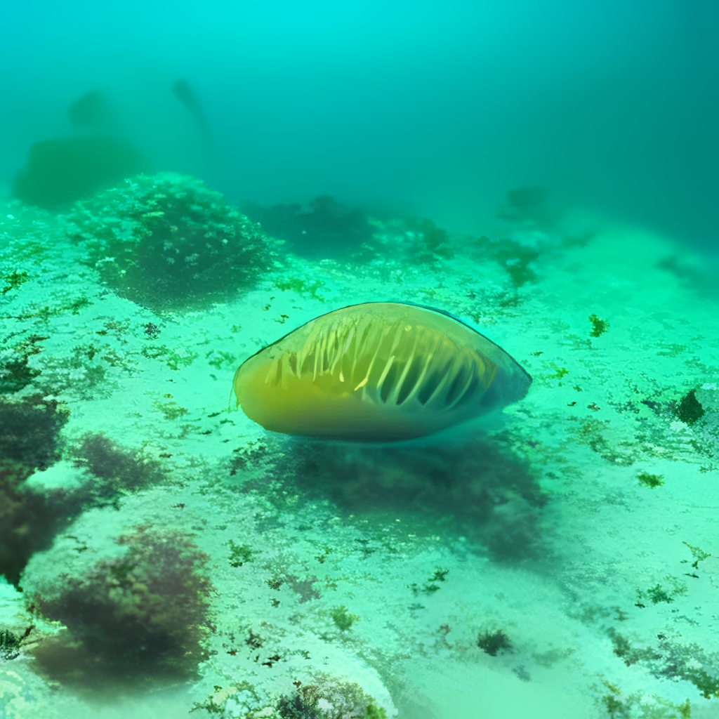
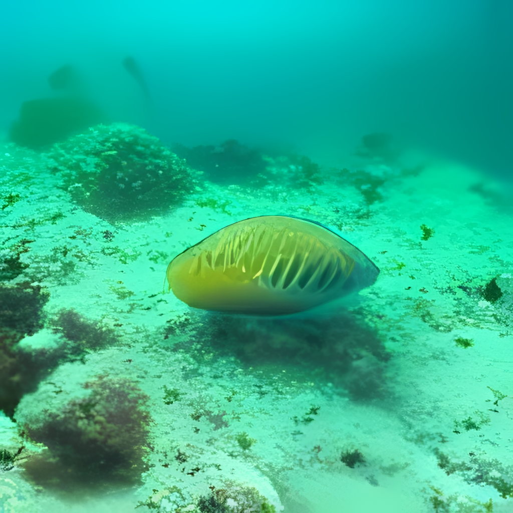
“Underwater life” from dalle-playground (Dalle mini)“Underwater life” from Optimised Stable-Diffusion
Content
Requirements
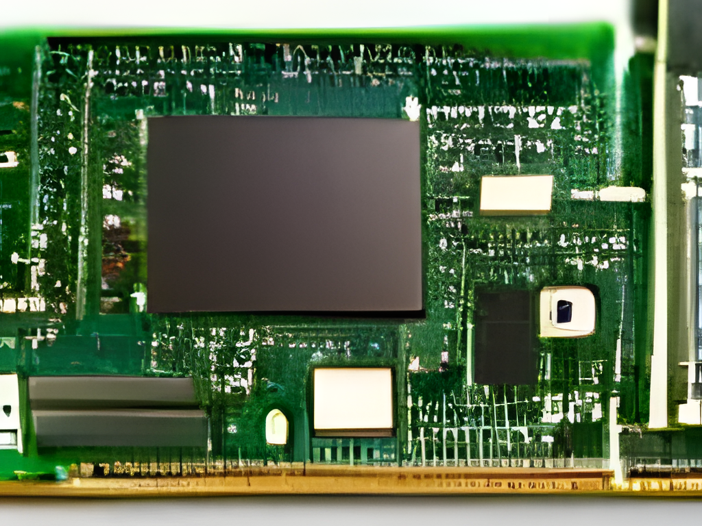
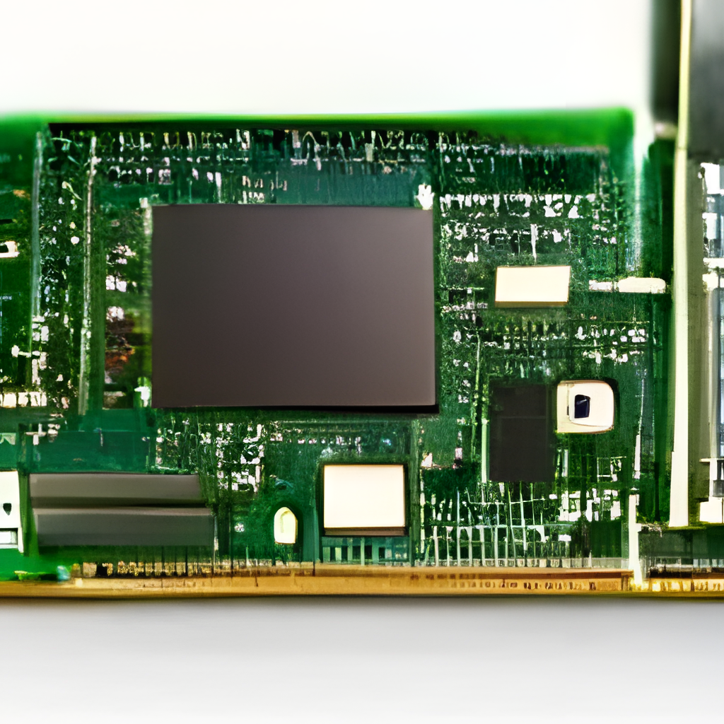
"Computer hardware elements" by dalle-playground
Hardware
Just for you to picture it, Pixray recommends a minimum 16GB of VRAM and Dalle-Flow 21GB. VRAM or virtual RAM is the rapid access memory in your graphics card (don't confuse it with the usual RAM memory).
A standard laptop like mine has a Nvidia GeForce GTX1050Ti with 3GB dedicated VRAM, plus 8GB RAM on board.
With this minimum requirement, and some patience, you can run Dalle-playground locally in your PC, although it also requires an internet connection to check for updated python modules and AI checkpoints.
If you have one or several more powerful graphic cards, I would recommend trying Pixray, as it installs relatively easy and it's well documented and extended.
Software requirements aren't trivial either. You'll need python and Node.js. I will show the main steps for Linux, which is more flexible when installing all kinds of packages of this kind, but this is equally valid for Windows or Mac if you manage yourself on a terminal or using docker.
Download dalle-playground
I found this repository by chance, just before it was updated for Stable Diffusion V2 (back in November 2022) and I was smart enough to clone it.
Access and download all the repository from my github:
All the algorithm works in python in a backend. The main repository only mentions the use of python3, so I assume that previous versions wont work. Check your python version with:
>> python3 -V
Python 3.10.6
Or install it from its official source (it's currently on version 3.11, so check which is the latest available for your system):
You'll also need the venv module to virtualize dalle-playground's working environment so it won't alter the whole python installation (the following is for Linux as it's included in the Windows installer):
sudo apt-get install python3.10-venv
In the backend folder, create a python virtual environment, which I named after dalleP:
cd dalle-playground/backend
python3 -m venv dalleP
Now, activate this virtual environment (you'll see that the name appears at the start of the terminal line):
(dalleP) abc@123: ~dalle-playground/backend$
Install the remaining python modules required by dalle-playground which are indicated in the file dalle-playground/backend/requirements.txt
pip3 install -r requirements.txt
Apart from this, you'll need pyTorch, if not installed yet:
pip3 intall torch
Install npm
Node.js will run a local web server which will act as an app. Install it from the official source:
Now move to the frontend folder dalle-playground/interface and install the modules needed by Node:
cd dalle-playground/interface
npm install
Launch the backend
With all installed let's launch the servers, starting with the backend.
First activate the python virtual environment in the folder dalle-playground/backend (if you just installed it, it should be activated already)
cd dalle-playground/backend
source dalleP/bin/activate
Launch the backend app:
python3 app.py --port 8080 --model_version mini
The backend will take a couple of minutes (from 2 to 5 minutes). Wait for a message like the following and focus on the IP addresses that appear at the end:
--> DALL-E Server is up and running!
--> Model selected - DALL-E ModelSize.MINI
 * Serving Flask app 'app' (lazy loading)
 * Environment: production
   WARNING: This is a development server. Do not use it in a production deployment.
   Use a production WSGI server instead.
 * Debug mode: off
INFO:werkzeug:WARNING: This is a development server. Do not use it in a production deployment. Use a production WSGI server instead.
 * Running on all addresses (0.0.0.0)
 * Running on http://127.0.0.1:8080
 * Running on http://192.168.1.XX:8080
Launch frontend
We'll now launch the Node.js local web server, opening a new terminal:
cd dalle-playground/interfaces
npm start
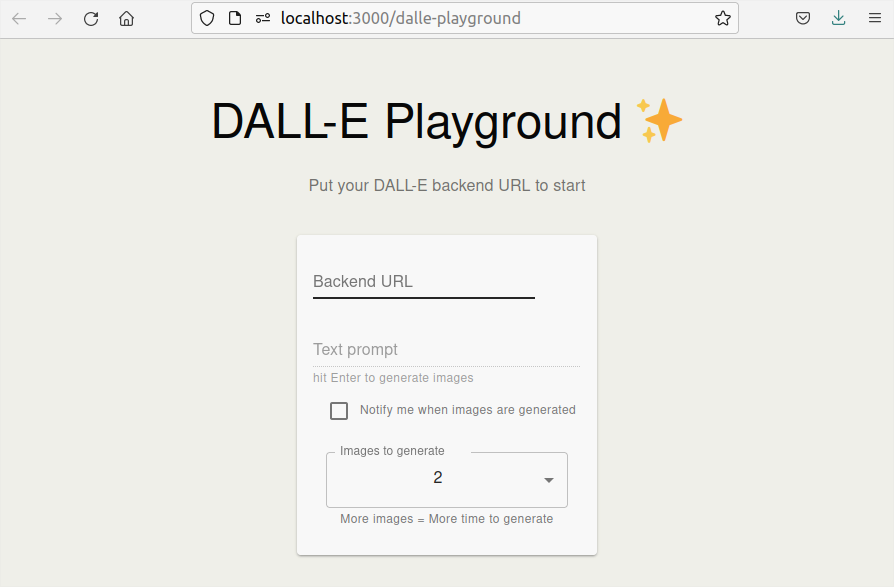
When the process finishes, it will launch a web browser and show the graphical interface of the app.
Automatic launcher
In Linux you can use my script launch.sh which starts backend and frontend automatically following the steps above. Just sit and wait for it to load.
launch.sh
#!/bin/bash
#Launcher for dalle-playground in Linux terminal

#Launchs backend and frontend scripts in one go
$(bash ./frontend.sh && bash ./backend.sh &)

#Both scripts will run in one terminal.
#Close this terminal to stop the programm.
backend.sh
#!/bin/bash
#Backend launcher for dalle-playground in Linux terminal

#move to backend folder
echo "------ MOVING TO BACKEND FOLDER ------"
cd ./backend

#set python virtual environment
echo "------ SETTING UP PYTHON VIRTUAL ENVIRONMENT ------"
python3 -m venv dalleP
source dalleP/bin/activate

#launch backend
echo "------ LAUNCHING DALLE-PLAYGROUND BACKEND ------"
python3 app.py --port 8080 --model_version mini &
frontend.sh
#!/bin/bash
#Frontend launcher for dalle-playground in Linux terminal

#move to frontend folder
echo "------ MOVING TO FRONTEND FOLDER ------"
cd ./interface

#launch frontend
echo "------ LAUNCHING DALLE-PLAYGROUND FRONTEND ------"
npm start &
App dalle-playground
In the first field, type the IP address for the backend server that we saw earlier. If you're accessing from the same PC, you can use the first one:
http://127.0.0.1:8080
But you can access from any other device in your local network using the second one:
http://192.168.1.XX:8080
Now introduce the image description to be generated in the second field, and choose the number of images to show (more images will take longer).
Press [enter] and wait for the image to generate (about 5 minutes per image).
And there you have your first local AI generated image. I will include a small gallery of results below. And in the next post I will be showing how to obtain better results using Stable Diffusion, also for lower than 4GB VRAM.
You know I await your doubts and comments on 🐦 Twitter!
I had a Shelly Dimmer inside a plug box in the wall, but one good day it stopped working (probably because of high temperatures, as it stands up to 35ºC). Looking for an alternative, I found Sonoff had released their equivalent for 1/3 the price of Shelly.
But in the end, cheap turns expensive, as it is much more complicated to configure than Shelly Dimmer and it has a bigger size.
After many tests, and given the poor documentation, here I explain how to configure Sonoff D1 Dimmer to use the local API without depending on the e-weLink app.
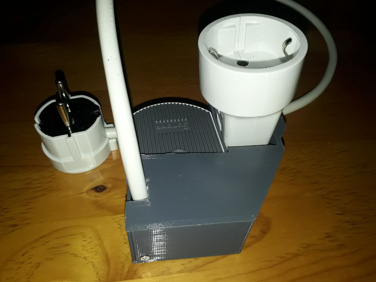
Additionally, given its size, you wont find much space for it in your connection boxes, so I’ll give you the idea to craft an external connection expansor.
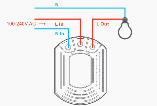
The previous schematic more or less complies with European norm:
Line (positive): black, brown or grey (red in this case...)
Neutral (negative): blue.
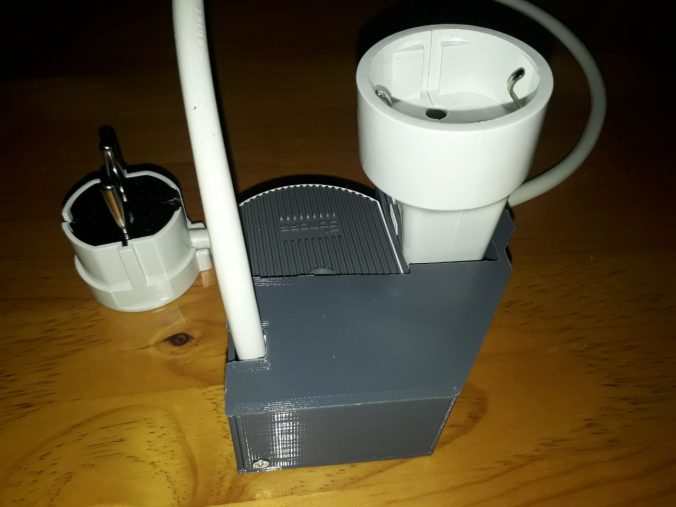
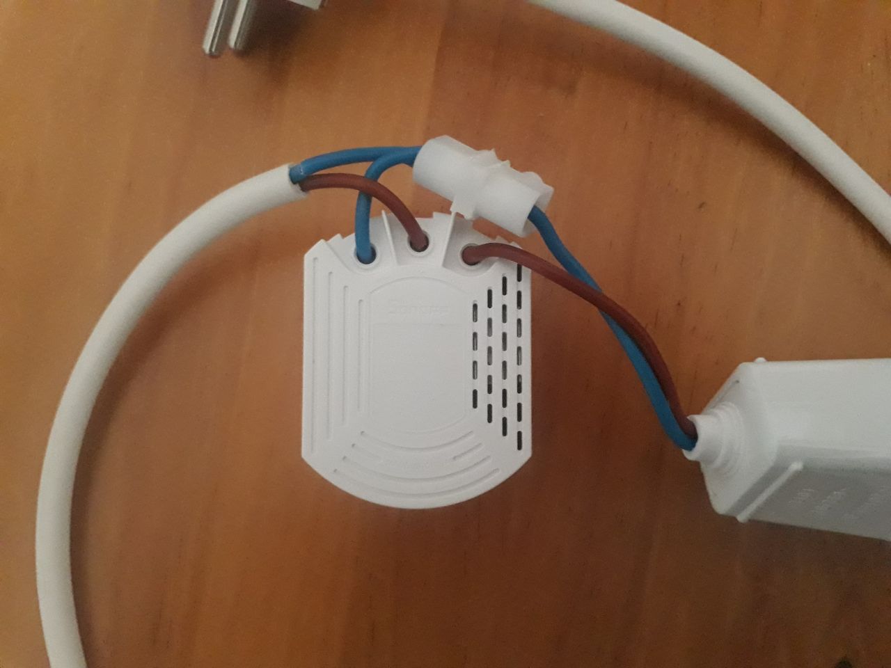
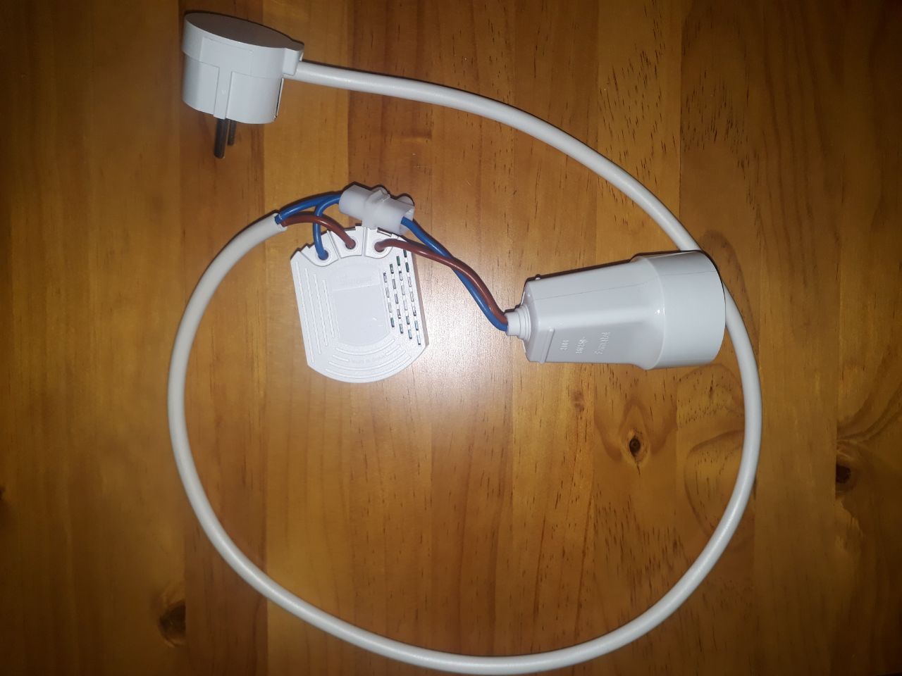
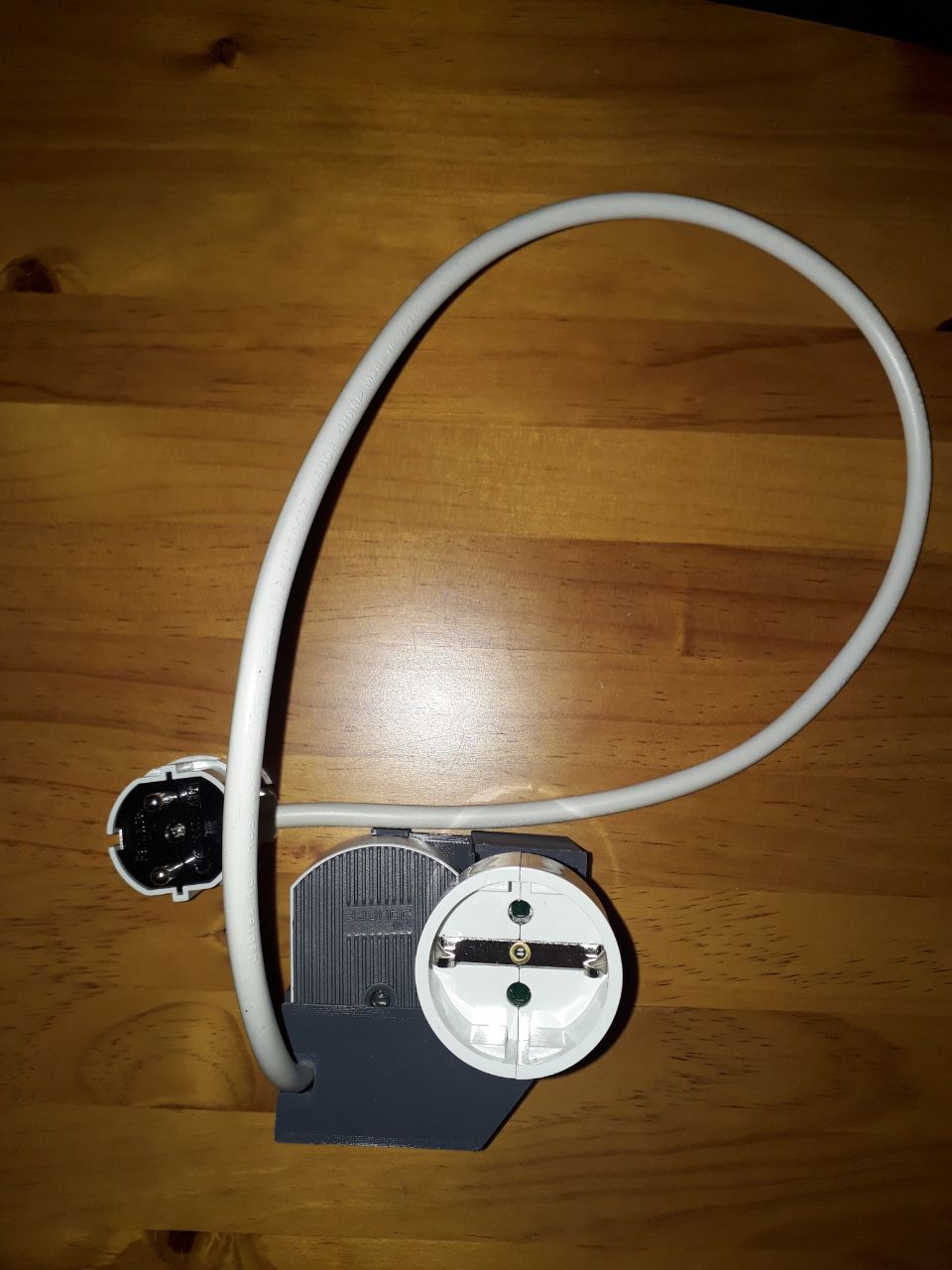
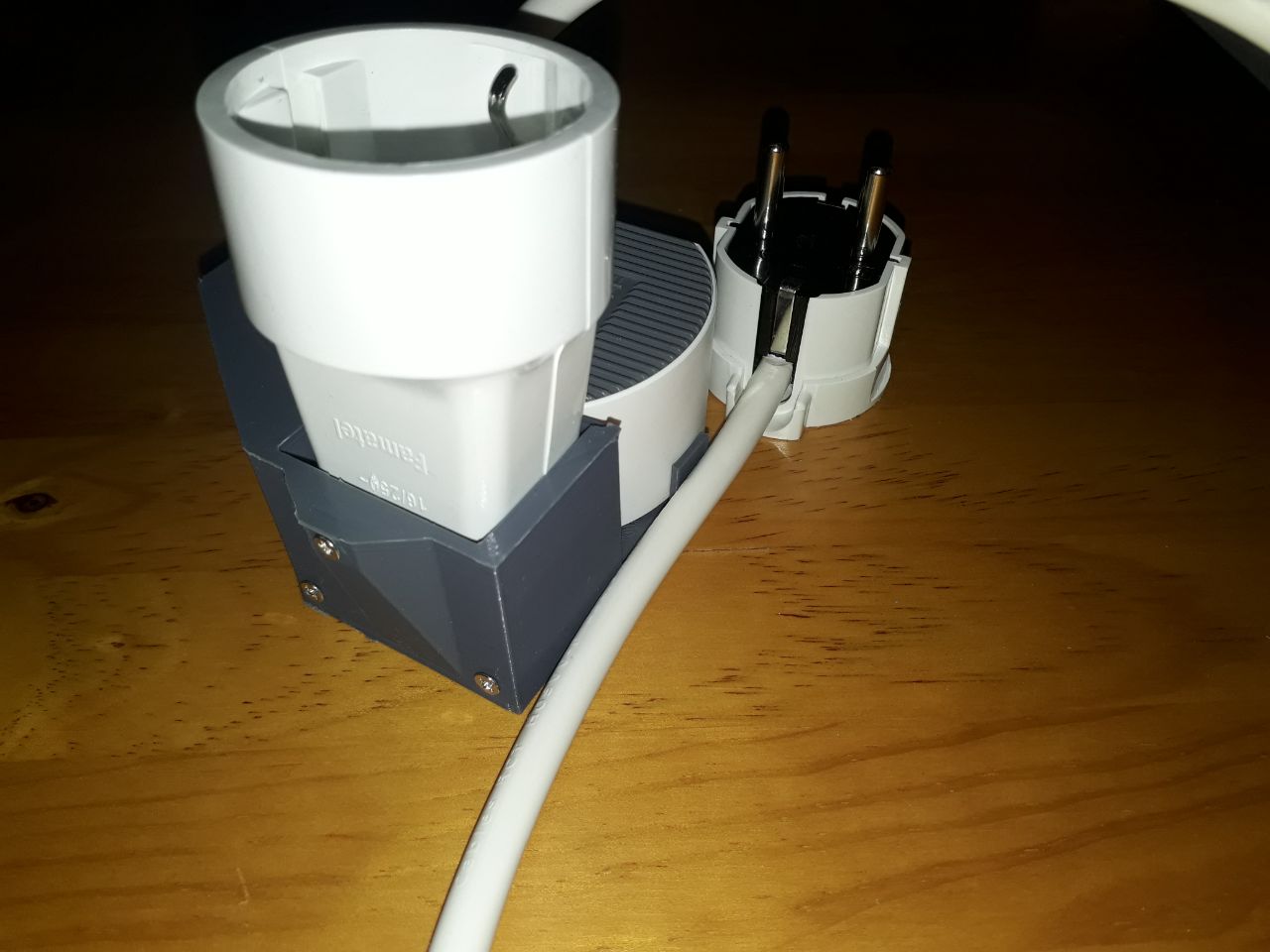
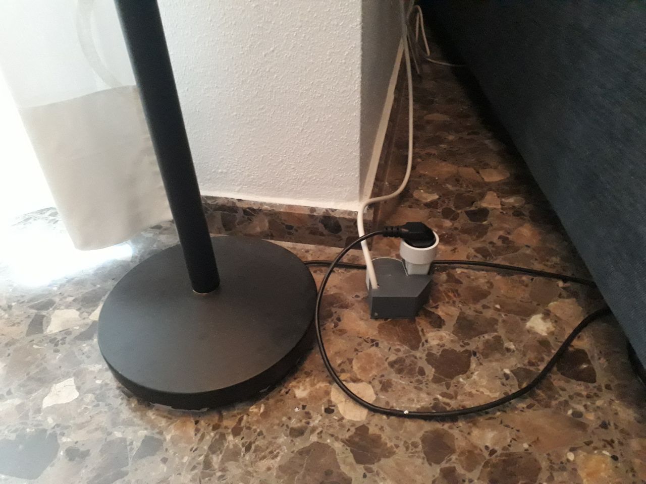
Shelly Dimmer is much more compact and fits easily in a connection box. But not in this case, so I will connect it externally using an extension lead, and I will later detail a simple case for its assembly.
TIP! If you're not experienced in electricity, you should review quite a bit and move forward with caution. It's not nice to have a shock with the domestic network. If you do the connection externally this way you won't be in much danger.
For the moment we can now make it work.
Internet connection
This is the complicated bit, as with so much casing, apparently there was no place for the usual pushbutton to power on/off and restore the device.
If you're lucky, your Sonoff wont be preconfigured and you might be able to connect to it on the first attempt. If it's preconfigured, probably to check its operation in another network, the device is no longer accessible even with the e-weLink app, unless you are in the network where it was configured.
To detect it, you must restore to default settings and for this you have two options:
Restore using e-weLink app from the network where it was configured (very unlikely you have access to it).
Restore using Sonoff RM-433 remote controller (you'll end up buying this extra accessory).
Pairing Sonoff RM-433 remote controller
In the end, the cheap D1 price has doubled with the need to buy the RM-433 remote controller, but the price is still not mad. Here is its manual:
The first thing to do is to pair the controller with the D1:
Connect the D1 to a socket.
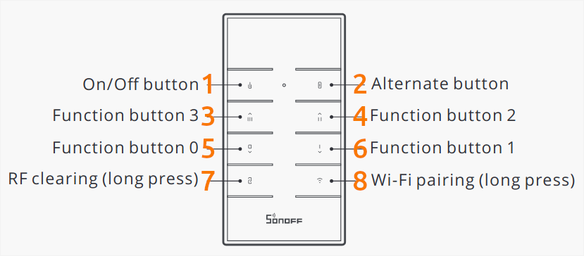
Hold button 7 for some 5 seconds, until you hear a beep (this removes the previous radio-frequency assignment).
Unplug and plug the D1 to get it restarted.
Press any button on the controller so it's assigned to the D1.
You'll hear another beep and the controller is now paired and can be used to control the D1.
Restore WIFI network
Now you need to restore the network assigned to the D1.
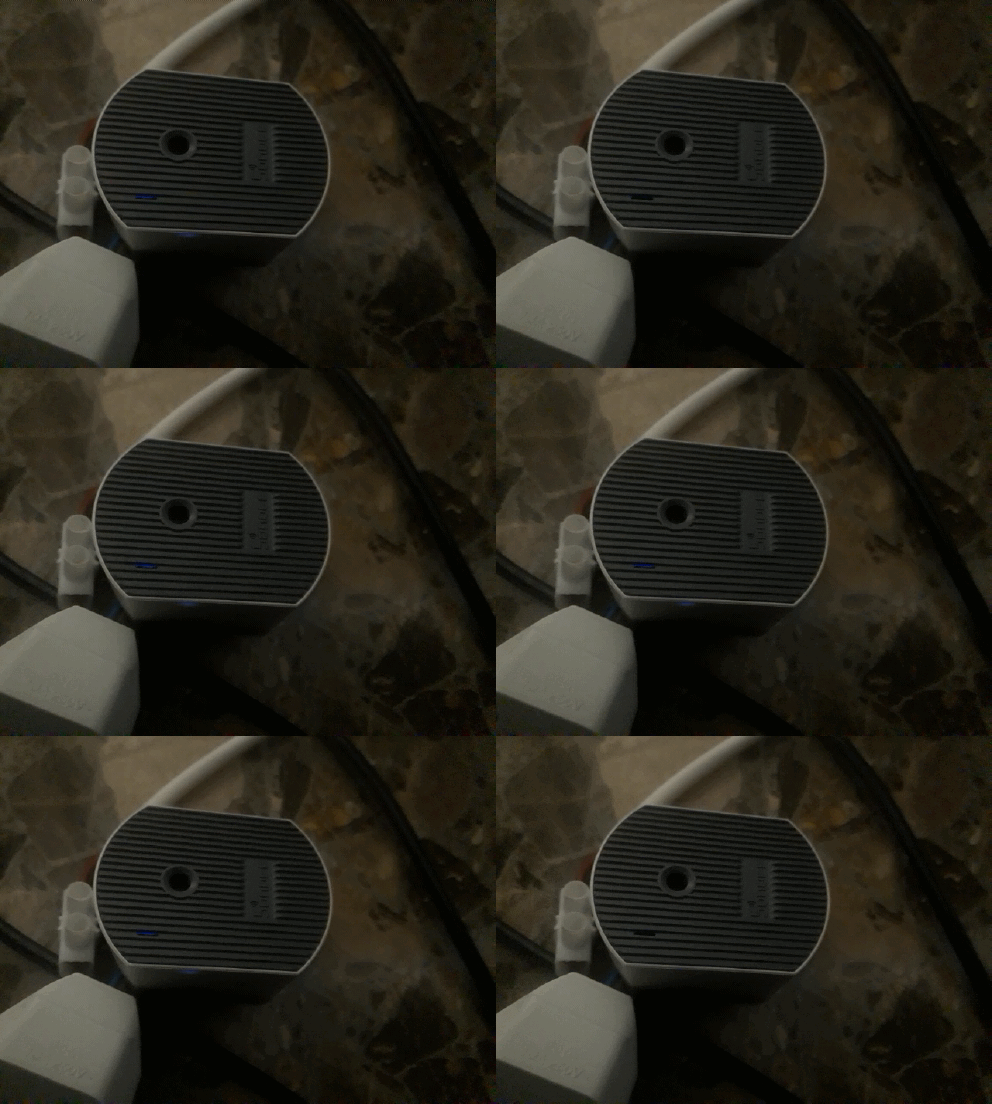
Hold button 8 for some 5 seconds, or basically, until the led starts blinking this way:
Breathing mode. Two fast blinks, one slow blink.
You removed the previous network. Now set it to pairing mode.
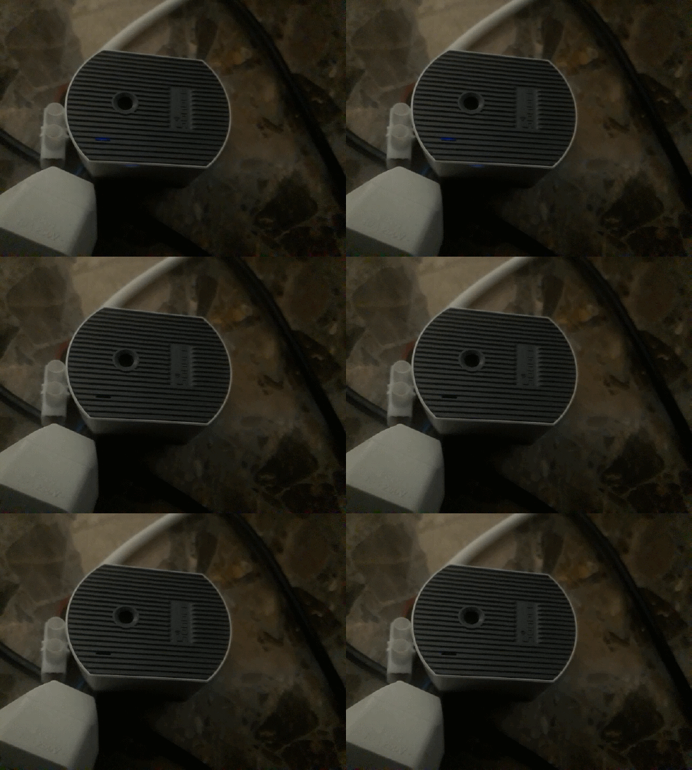
Again, hold button 8 for some 5 seconds, or until the led starts blinking continuously:
Pairing mode. Constant blinking.
This way, the device starts a WIFI Access Point (WIFI AP) with a name in the form ITEAD-XXXXXXXXXX.
Pairing with e-weLink
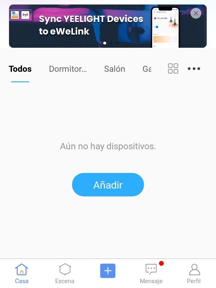
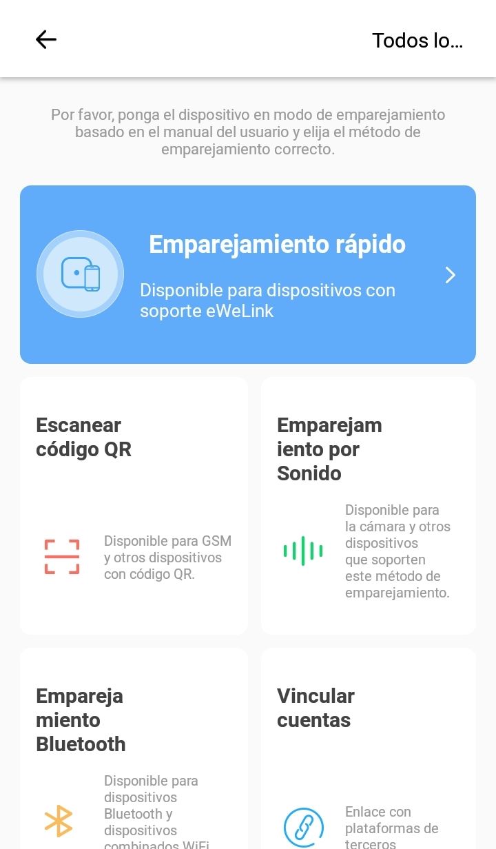
From here, if you want the easy route, just download the e-weLink app and press the quick pairing button. You'll then have your D1 accessible from this app.
Pairing in DIY mode
But I want the complicated way and enable DIY mode to access the device network and control it using commands from the HTTP API in a web app.
We need to find the WIFI network named ITEAD-XXXXXXXXXX set up by the device and connect to it using the password 12345678.
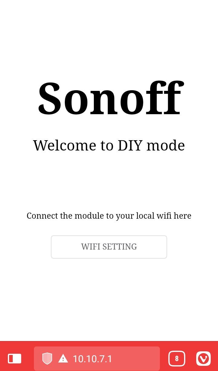
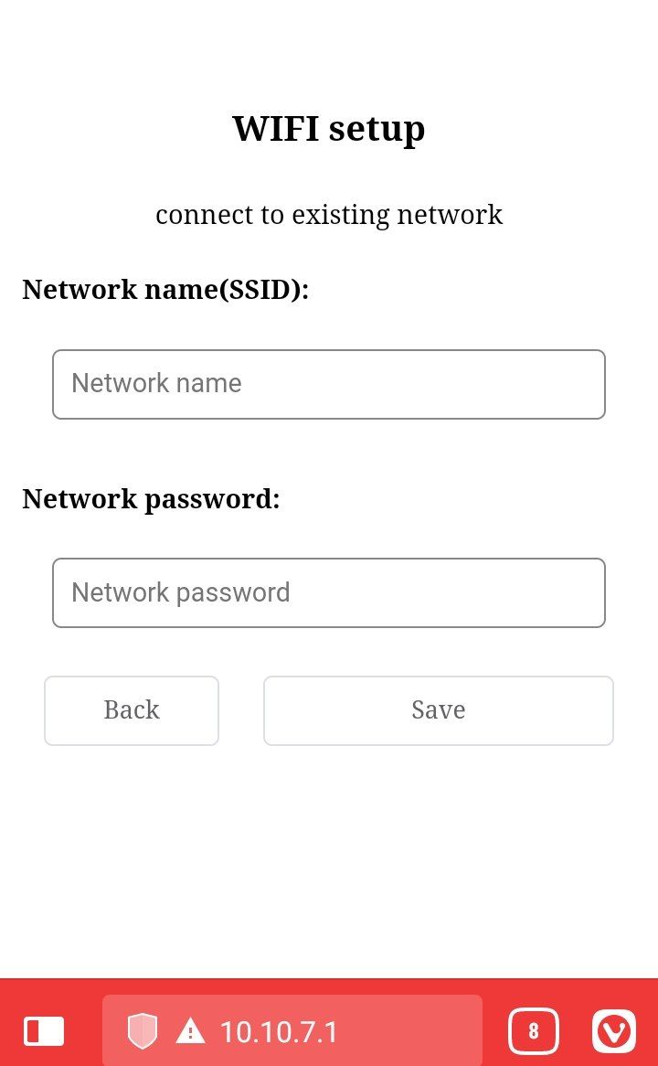
Now open a web browser and access this address http://10.10.7.1 where you'll find the following screens.
Introduce the name (SSID) and password of your WIFI network, and the device is now linked to it.
Assembly
Before getting into the detail of the HTTP API, I'll show you a 3D printed case design to avoid the cables and connections being completely exposed.
It consists of two PLA pieces (base and top) which can be screwed together and which you can download from this server:
To use the command of the HTTP API you must know the device IP in your local network.
Find IP in the router
You can access the network map in your router, usually from the address http://192.168.1.1
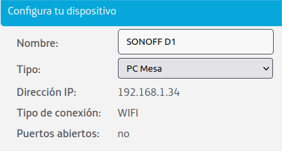
The address and the password should be in some sticker in your router. Then you'll see your device with a name like ESP-XXXX which derives from the WIFI module it holds (I already renamed it here):
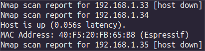
Find IP using nmap
In a terminal you can use the tool nmap to scan your local network.
Download it if not done yet: sudo apt-get update sudo apt-get install nmap
Scan your network (using sudo you'll get the MAC address, which is useful as the IP could change when restarting the router) sudo nmap -v -sn 192.168.1.0/24
Send HTTP requests to the D1
Sonoff's D1 HTTP API is documented in their website:
In order to communicate with the device, you need to send HTTP requests using some software like Postman or using curl or wget in a terminal.
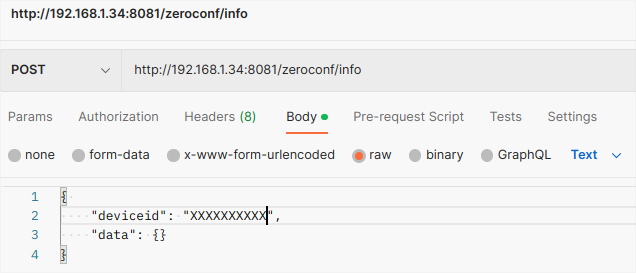
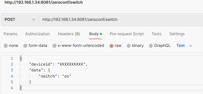
The request is sent to the device IP, to the default port 8081, and we also have to include the device id in the request body (this id matches the XXXXXXXXXX coding in the WIFI network name ITEAD-XXXXXXXXXX).
Let's see some use cases with curl and Postman.
Device information
http://[ip]:[port]/zeroconf/info
curl
curl -X POST 'http://192.168.1.34:8081/zeroconf/info' --data-raw '{"deviceid": "XXXXXXXXXX","data": {}}'
curl -X POST 'http://192.168.1.34:8081/zeroconf/switch' --data-raw '{"deviceid": "XXXXXXXXXX","data": {"switch":"on"}}'
Postman
Response
{
    "seq": 9,
    "error": 0
}
Brightness adjustment
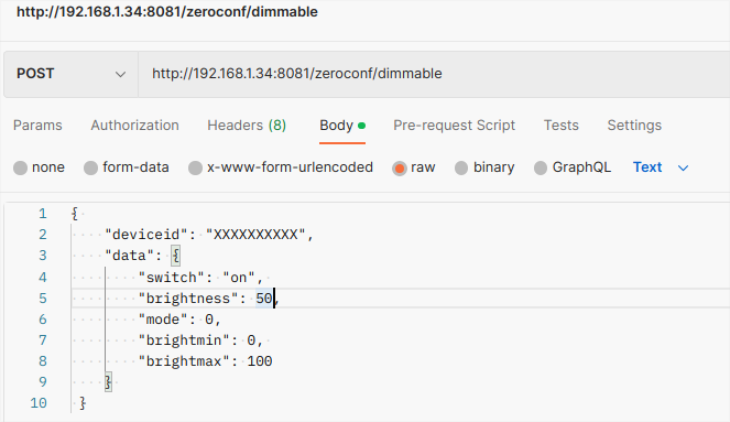
http://[ip]:[port]/zeroconf/dimmable
curl
curl -X POST 'http://192.168.1.34:8081/zeroconf/dimmable' --data-raw '{"deviceid": "XXXXXXXXXX","data": {"switch":"on","brightness":50,"mode":0,"brightmin":0,"brightmax":100}}'
Postman
Response
{
    "seq": 14,
    "error": 0
}
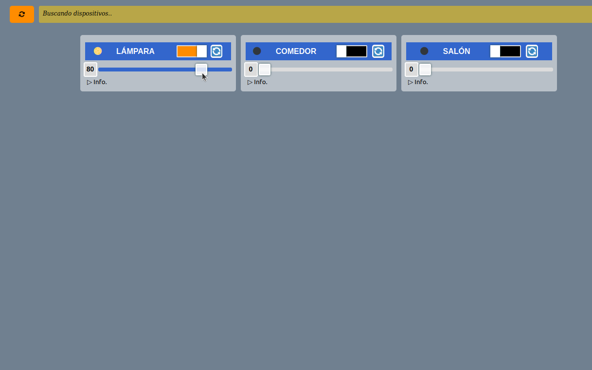
Now you're ready to program your own app and control your D1 to your like in a completely private way. I hope this was useful, but if you find any doubts or comments, don't hesitate to drop them on Twitter 🐦!
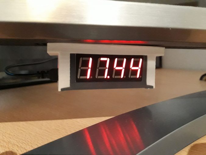
After lots of comings and goings, trials, redesigns, burnts, cuts and some minor explosions, finally I can bring a smart desktop clock I have been working on for the last 2 years. Making a detailed tutorial can be even longer and tedious, so I hope these traces can help make your own. I warn you this takes a lot of time and practice, and can’t be done carelessly…
Content
What's Temps-i 7?
Let's break down its name:
Temps mean time in the Valencia dialect,
i for internet, where it gets the time,
7 for the display, which uses 7 segments for every digit.
These three concepts define this compact desktop clock, with WIFI connectivity, temperature sensor and good autonomy.
Let's see how it's made!
Components
First, let's see the recipe ingredients and what each one does:
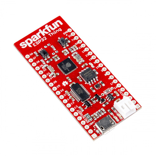
Sparkfun ESP32-Thing board >>Top performance microcontroller with WIFI and Bluetooth connectivity thanks to the ESP32 integrated chip, ideal for IoT projects.
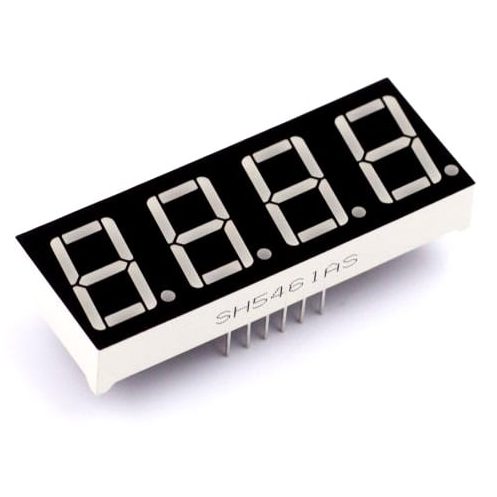
4 digits 7 segments red color display. >>Shows time and temperature.
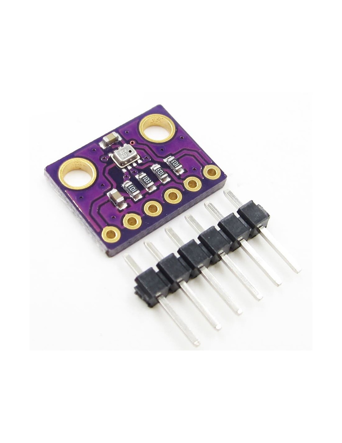
BMP-280 module. >>Temperature and barometric pressure compact digital sensor.
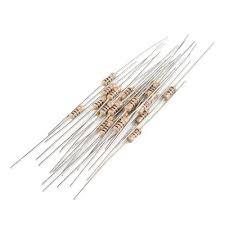
100 Ohm resistors >>Needed to reduce display current, without lowering brightness excessively (admits up to 1k Ohm, but leds would be hardly visible with daylight).
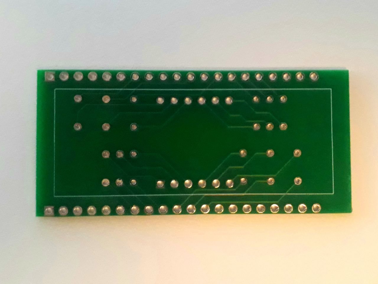
PCB with custom circuit. >>Simplifies display and resistors connectiont to the microcontroller.
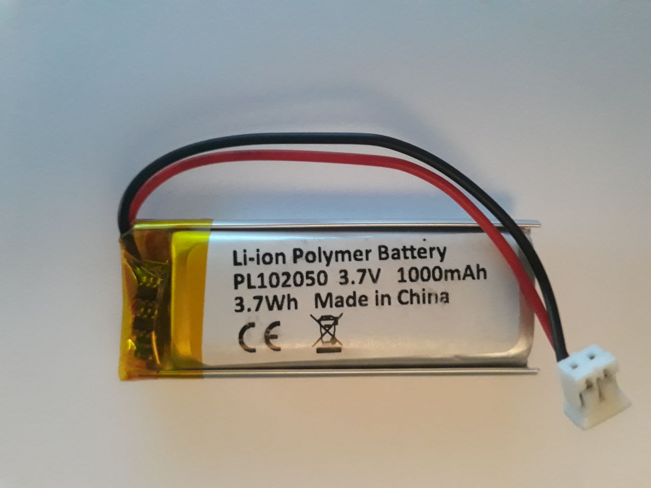
1000mAh 3.7v LiPo battery >>Ensures an autonomy up to 48 hours without external voltage.
Jumper cables. >>For additional connections of external modules.
Push button >>Used to switch the program on display.
Electronic design
It's very important to study the electronic components being used, read all the specifications and prototype with all precautions before we start soldering like crazy.
Component selection
The components listed earlier are not a mere coincidence or copied from elsewhere. They're the most successful trial of many others and meets the project needs:
The 4 digit display shows exactly what I'm after: the time. If I can also use it to show temperature, that's fine. But a better quality display, like LCD, would be unnecessarily demanding, and autonomy is another key requirement.
The microcontroller includes internet connectivity, as well as enough computing capacity. It also has sufficient in/out pins to control the display without a gpio expansor. Some other options I've tried:
More compact microcontrollers: Teensy 4, Digispark, SparkFun Pro Micro. They need a GPIO expansor (like PCF8574) and/or a WIFI module (like ESP-01). This also involves too many more connections.
Microcontrollers integrating WIFI and sufficient I/O, like NodeMCU ESP8266. Got out-dated and lacks processing capacity as the counter delayed almost 4 seconds every minute.
Prototyping electronic circuit
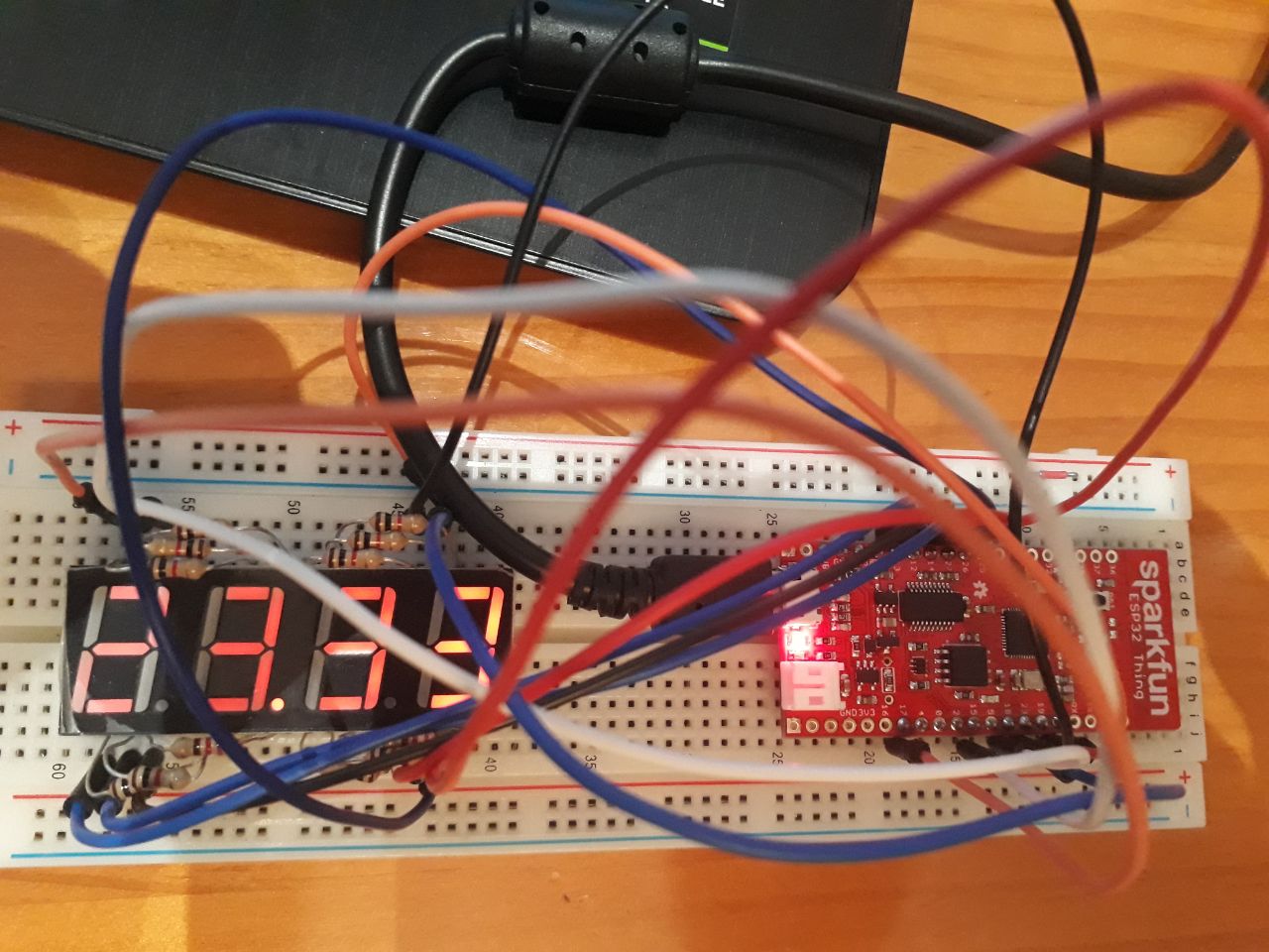
Having researched and obtained the components, connect them in a prototype board (protoboard) to test their operation.
In my case, after different pin combinations, the most organised way is the following:
ESP32-Thing
Component
VBAT
LiPo +
3V3
BMP-280 3V3
GND
LiPo - BMP GND BMP SD0 Push -
GPIO21
BMP SDA
GPIO04
BMP SCL
GPIO32
Push +
GPIO17
Display Digit 1
GPIO23
Display Digit 2
GPIO19
Display Digit 3
GPIO25
Display Digit 4
GPIO15
Display Segment A
GPIO22
Display Segment B
GPIO27
Display Segment C
GPIO12
Display Segment D
GPIO13
Display Segment E
GPIO18
Display Segment F
GPIO26
Display Segment G
GPIO14
Display Segment P (dot)
Pinout schematic
Once the prototype is achieved, you should save it in a schematic diagram using EDA software (electronic design automation) like Kicad, where you can also generate a PCB design that can be sent for manufacturing. Otherwise, you can always save the schematic in paper, as you wont remember where every cable was going in a couple months time...
Kicad is a bit tricky and it's good to practice with simpler projects. Despite this, it's quite manageable for medium users as it basically consists of searching and choosing symbols for our components and connect their pins accordingly to specifications.
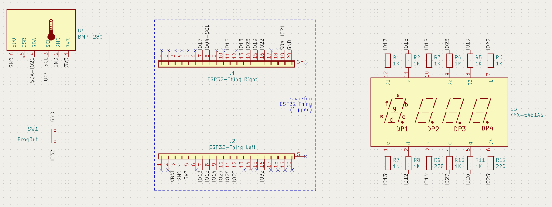
To avoid messing the sketch up with cables, I used names in every connection, which is also valid in Kicad. Also, you'll see that the ESP32-Thing is made up of two 20x pin headers, as I didn't find a working symbol and didn't have time to design one properly. What really matters is that the design is working and coherent with reality.
Kicad shematic
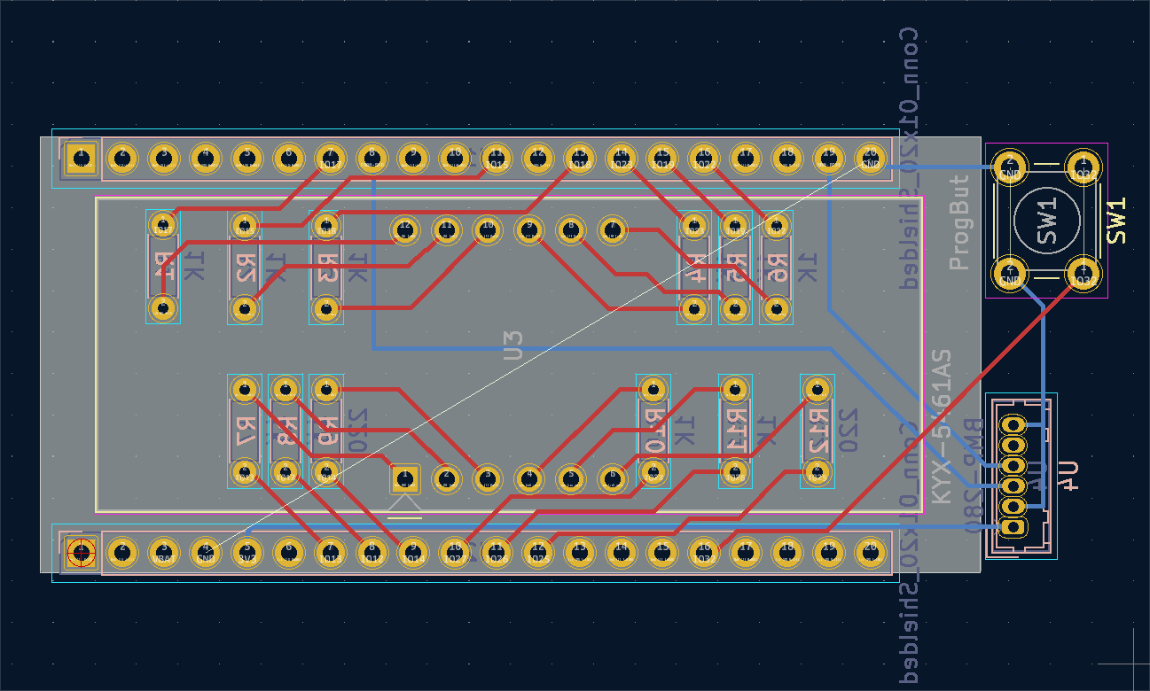
Next step is to assign footprints that are realistic for each symbol, so then we can design a printed circuit board that we can order (usually in China) for 15€ / 5 boards.
You don't need to go crazy on this, specially if you're not experienced. I only need to make soldering connections simpler, as in this case you need about 90 of them but keeping a compact design.
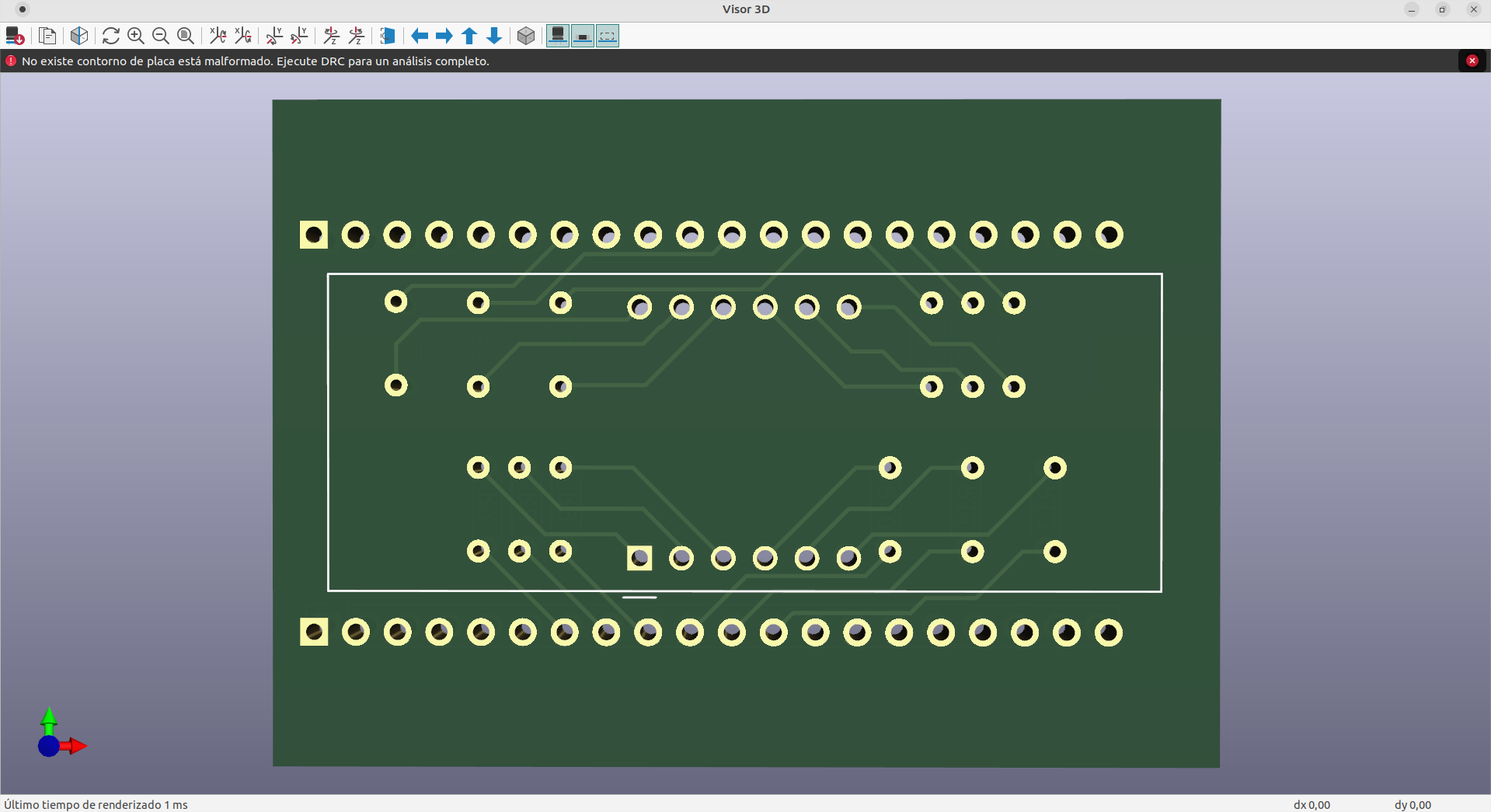
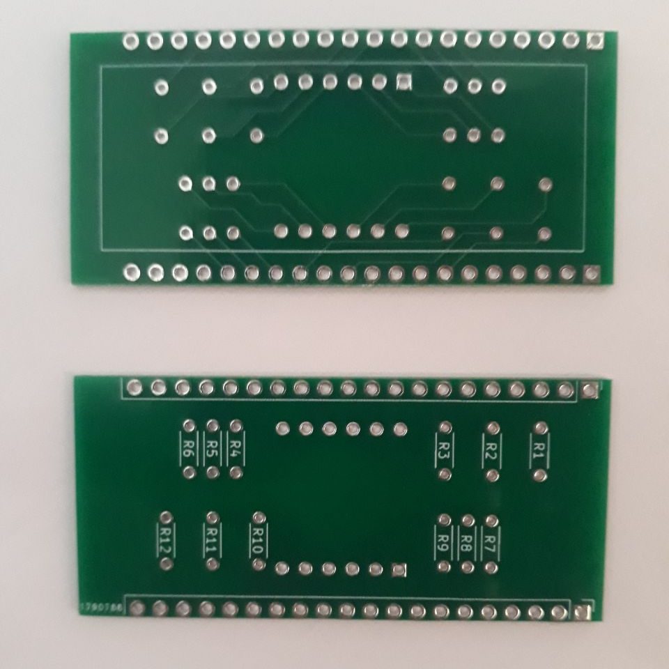
PCB design in KicadPCB 3D viewerOrdered PCBs
Clock programming
Most microcontrollers, like the ESP32-Thing, are compatible with the Arduino IDE, which makes it simpler to connect the board to a PC and load a clock program.
Before starting, it's important to make a list of tasks and functions that we want to include in the program and modify it as we code. This way you can try different functions separately and debug every step to find errors quickly. In my case, and after many trials, the program will consist of the following:
Define libraries and variables.
Configure pins.
Connect WiFi.
Get date via SNTP.
Disconnect and turn off WiFi (saves battery).
Convert date into digits.
Show digits on display.
Start timer.
Start reading program change pin.
Change program on pushbutton activation.
Read sensors.
Show temperature on display.
Update time after timer ending (every minute).
Restart timer.
I don't want to spend too long on the code, and it's also not the most tidy I have, but here it is for anyone who wants to copy it, and also on github:
Notice you'll need these additional libraries installed using the Arduino IDE:
esp32 board manager by Espressif
WiFiMulti library
Adafruit_BMP280 library
(the rest of the libraries derive from these ones)
You should constantly try the performance of the code during prototyping so you can change any pin assignment in case of any malfunctioning. If it's all soldered and something fails, it will be really hard to find and solve the error, if it's from a connection.
Assembly
Soldering
Once the code is checked and the PCB is designed, you can start soldering with caution, as a wrong movement can damage your modules or produce errors in the program.
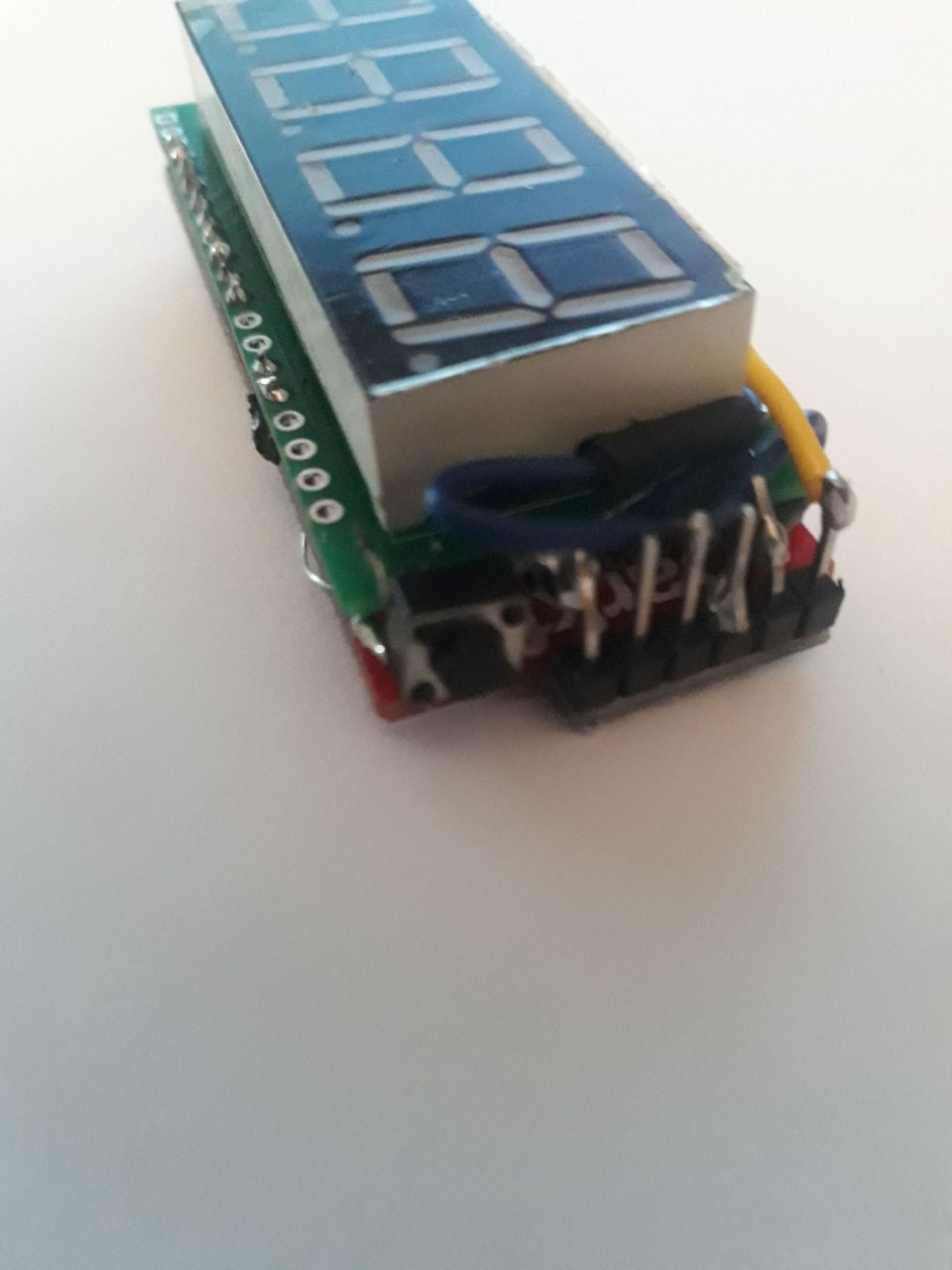
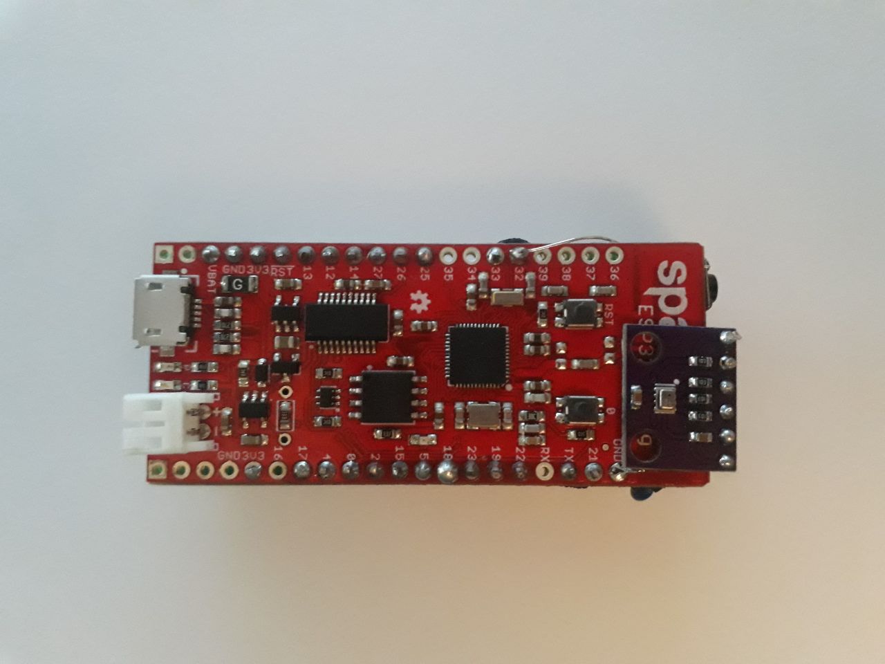
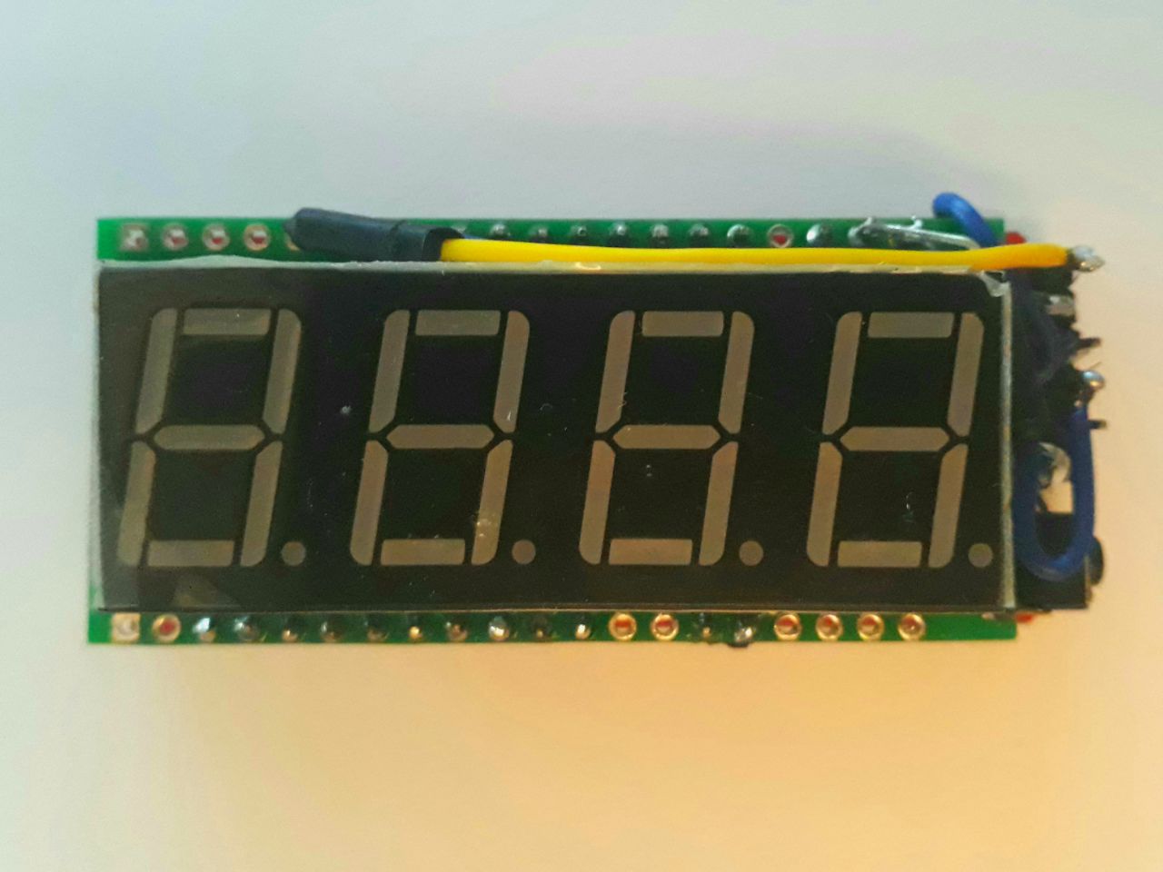
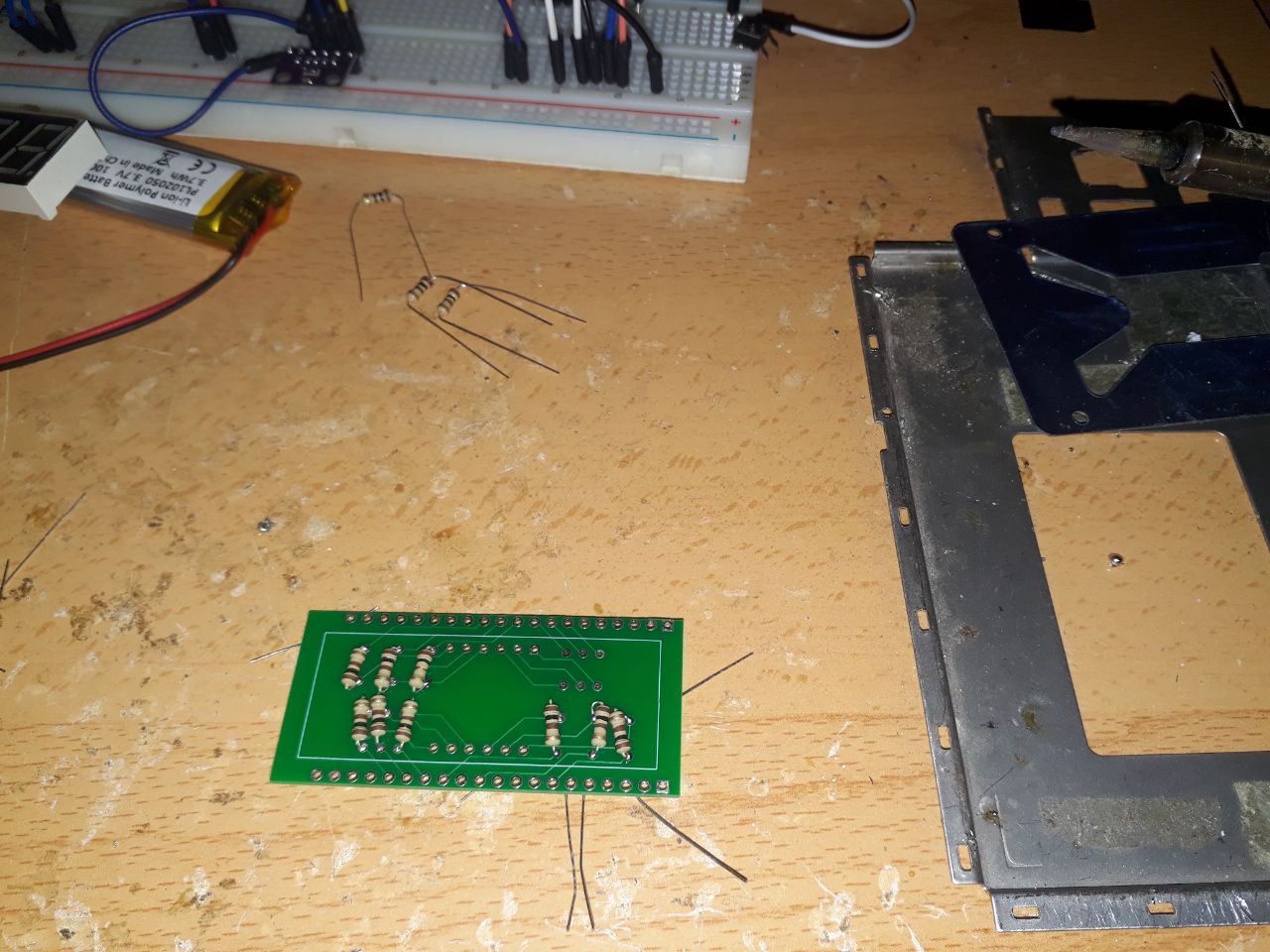
BMP-280 soldered to boardEsp32-Thing soldered to boardDisplay soldered to boardResistors soldered to board
Case design
Having it all soldered you'll have a better idea of the final volume of the device. I measure it all with precision using a digital caliper to make a 3D model of it.
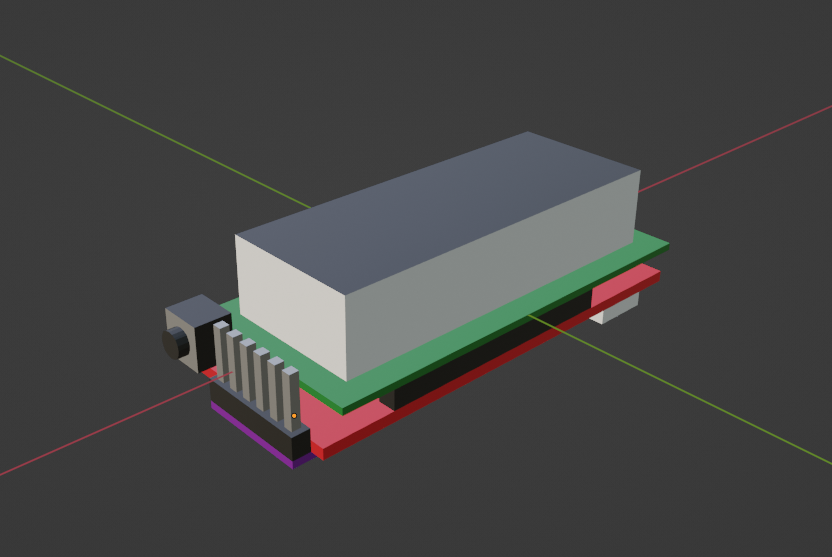
Blender 3D model of all components in their final position
This way you can now design a case around the model so you can craft it using a 3D printer. You could also use other types of assembling materials like plywood or metal.
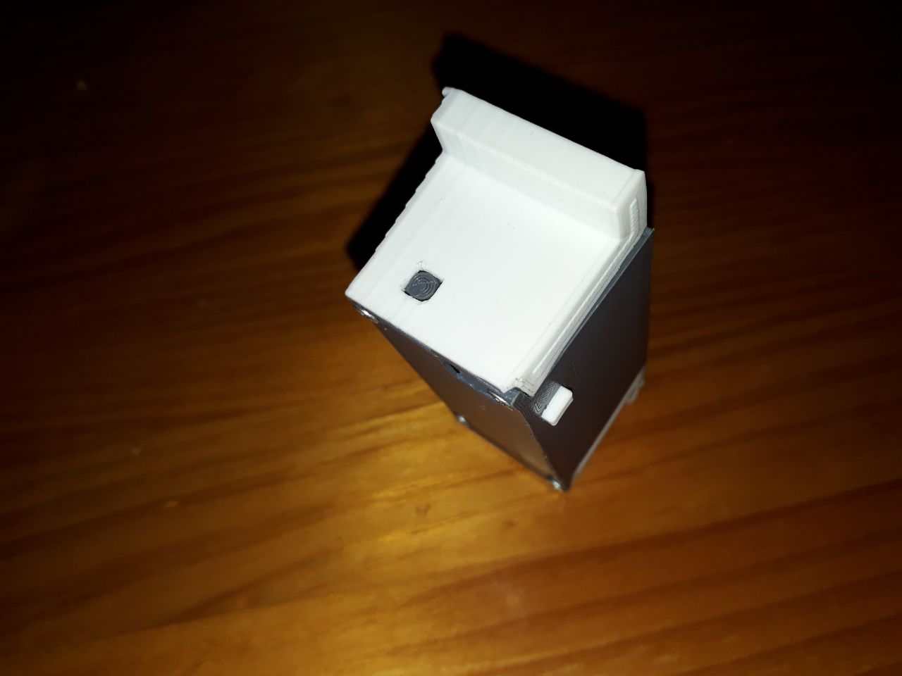
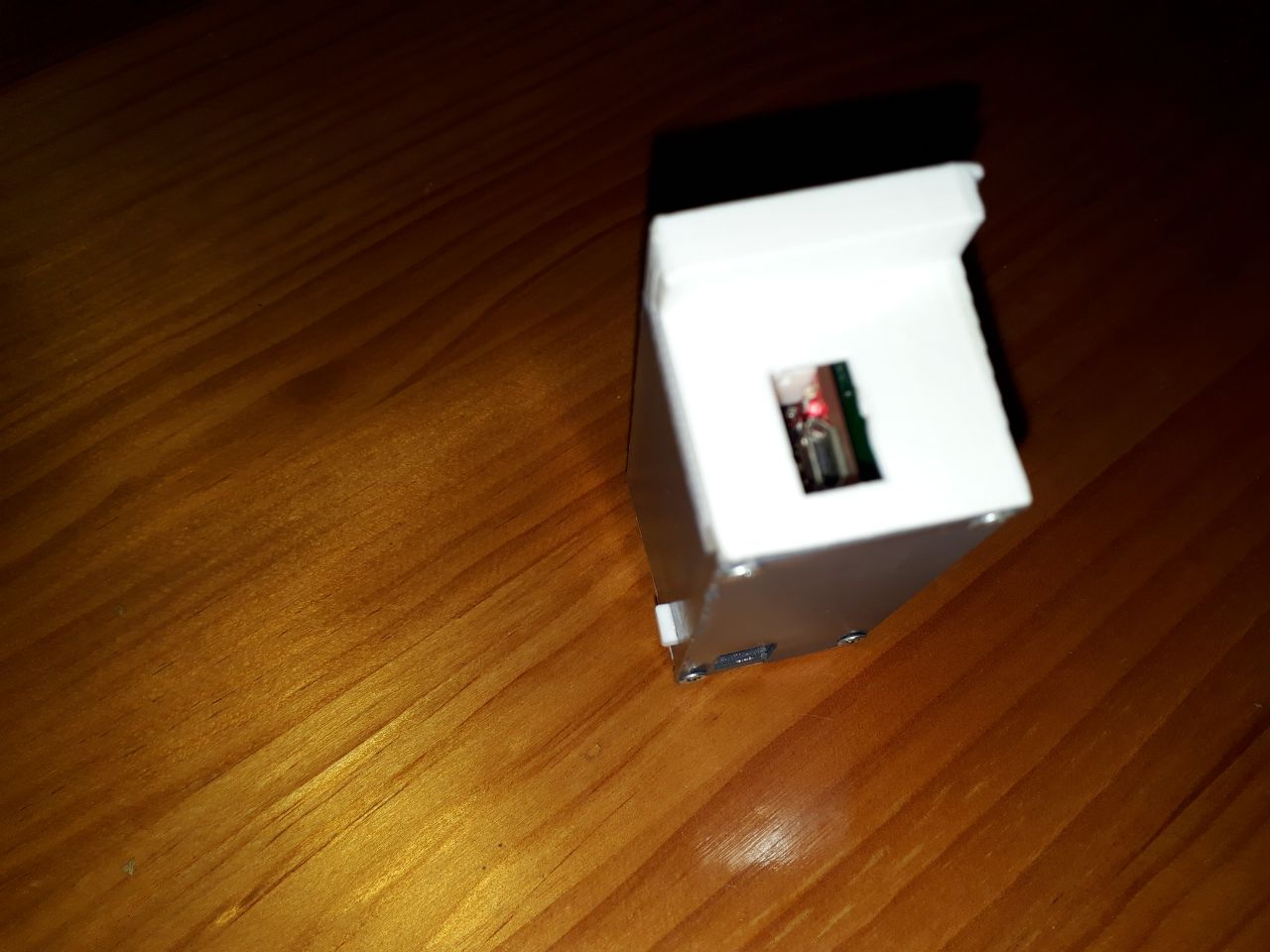
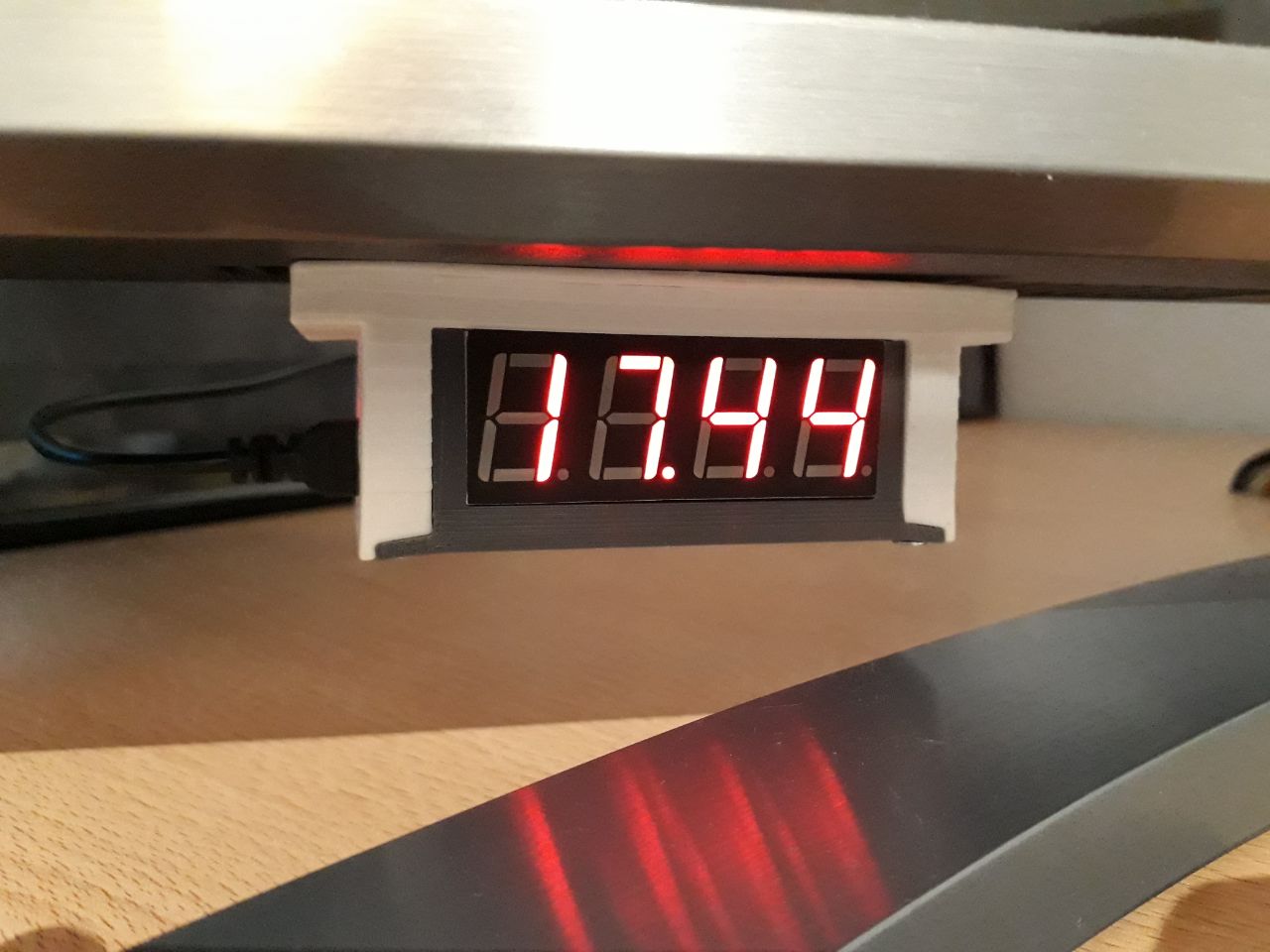
I usually craft two pieces (one as a base and another one as a cover) so they can be screwed together. I also include different voids to allow for the connection of the USB cable, to add the program switch button and to add a rotary support to hold the clock in a slot in the television.
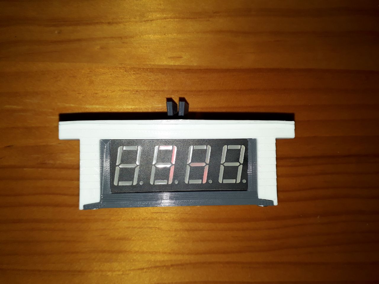
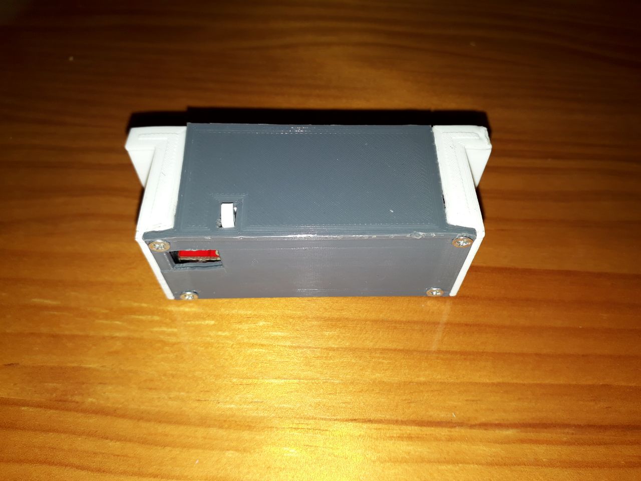
I will also use white PLA in one piece and grey in the other to bring more life to the design, ending it all like this:
And that's it. I hope you liked it and find it useful. Now you can get your own WIFI clock crafted! Any doubt about this clock can be dropped on Twitter! 🐦
Everything looks fine until you run the program and this happens:
>> unityhub
This error originated either by throwing inside of an async function without a catch block, or by rejecting a promise which was not handled with .catch(). The promise rejected with the reason:
ConnectionLost: Timeout! Cannot connect to Licensing Client within 60000ms
    at Function.fromType (/opt/unityhub/resources/app.asar/node_modules/@licensing/licensing-sdk/lib/core/ipc/licensingIpc.js:51:16)
    ...
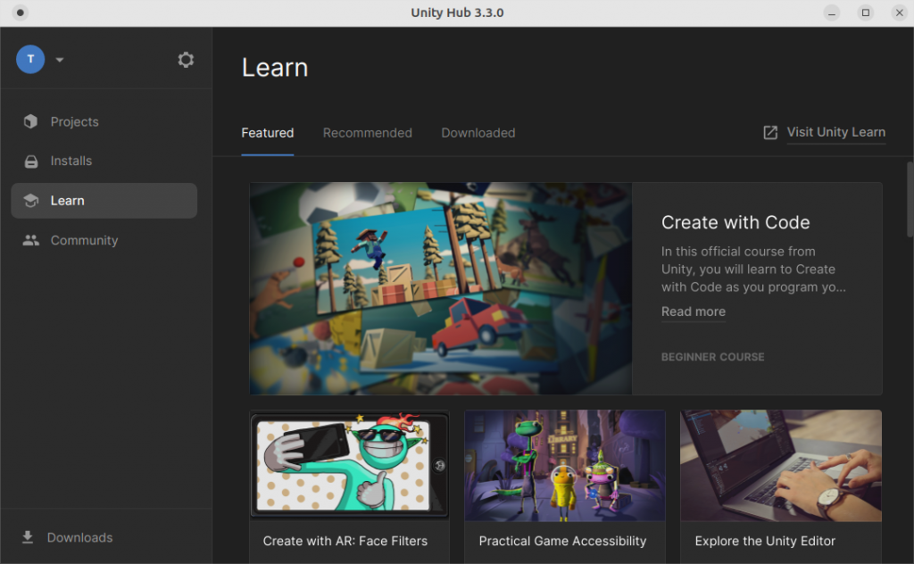
Luckily, surfing the web you usually find the solution, and this one was in the same Unity forum:
Following the official steps from their site (first link in the post):
Add the Unity repository to your sources list: sudo sh -c 'echo "deb https://hub.unity3d.com/linux/repos/deb stable main" > /etc/apt/sources.list.d/unityhub.list'
Add the public key to make it trustful: wget -qO - https://hub.unity3d.com/linux/keys/public | sudo apt-key add -
Update your repositories: sudo apt update
Install UnityHub: sudo apt-get install unityhub
It should all go fine, despite an error with some “chrome-sandbox” folder. But that’s not the error. Running unityhub from the terminal we have the above error.
Installing libssl1.1
The problem is that Ubuntu 22 uses a more recent version of libssl package, but we can still download the version used by Ubuntu 20.
I had this pending for a while, and by following some Tweets and the project GOIA by Iker Jiménez, it seemed that AI image generation had become really accessible. And it is. There’s enormous advance in this field. But it all has a price.
Image generation from OpenAI, one of Elon Musk giants, named after Dall·E, launched its open API for everyone to test.
It’s got 18$ credit to use during 3 months only by signing up. The rest needs to be paid, but you’ll have enough for making tests, and the it’s only 0.02$ per picture. Additionally it’s easy to use and the results are great.
It’s worth trying it to know what’s the top and at the end I will show you what we, the rest, of the mortals can use daily.
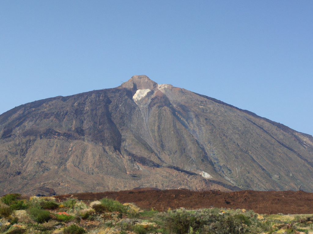
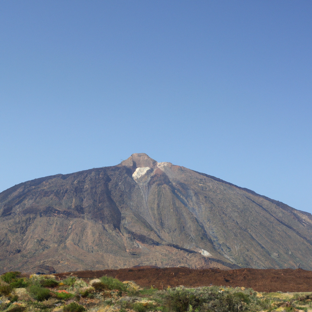
But first… let’s start with a picture of Teide volcano in Tenerife. Is it real or virtual?
Teide picture, Tenerife, created with Dall·E 2 by OpenAI. The Roaming Workshop 2022.
Content
OpenAI API
Ok, very quickly, OpenAI is the Artifitial Intelligence (AI) megaproject from Elon Musk & Co. Within the numerous capabilities of this neuronal networks, we can generate images from natural language text, but there's much more.
IA will make our life easier in the future, so have a look at all the examples that are open during Beta testing:
Basically, a computer is "trained" with real, well featured, examples so, from them, the computer generates new content to satisfy a request.
The computer will not generate exactly what you want or think, something expected, but it will generate it's own result from your request and what it has been learning during training.
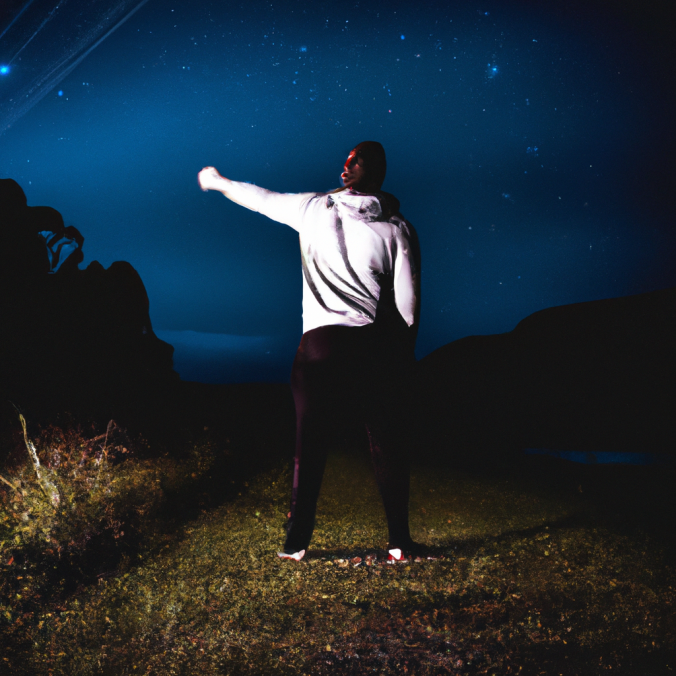
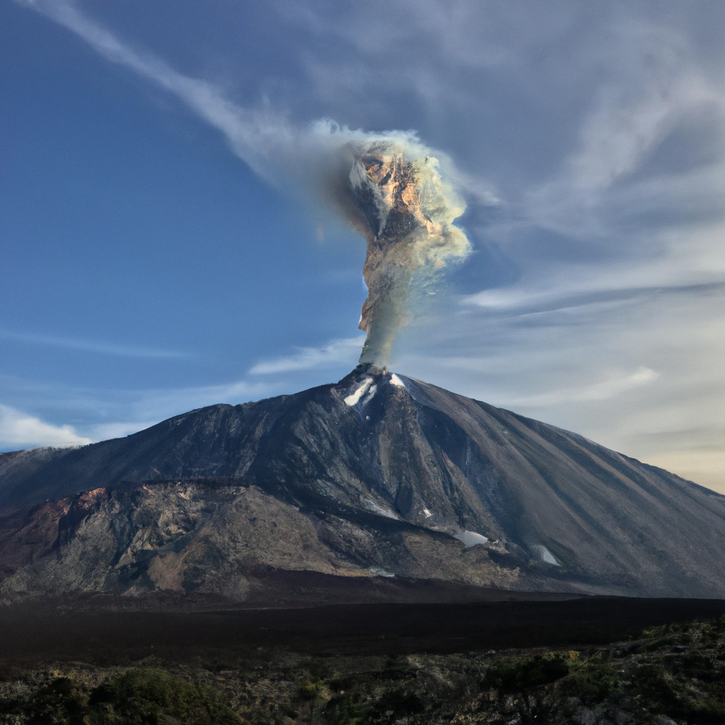
Image generation from natural language might the the most graphical application, but the potential is unimaginable. Up there I just asked Dall·E for the word "Teide". But, what if we think about things that have not happened, that we have not seen, or simple imaginations? Well, AI is able to bring to life your thoughts. Whatever you can imagine is shown on screen.
Teide erupction, according to Dall·E 2 by OpenAI. The Roaming Workshop 2022.
Now, let's see how to use it.
Dall·E 2 API
To "sell us" the future, OpenAI makes it very easy. We'll find plenty documentation to spend hours in a Beta trial version completely open for three months, and you'll only need an email address.
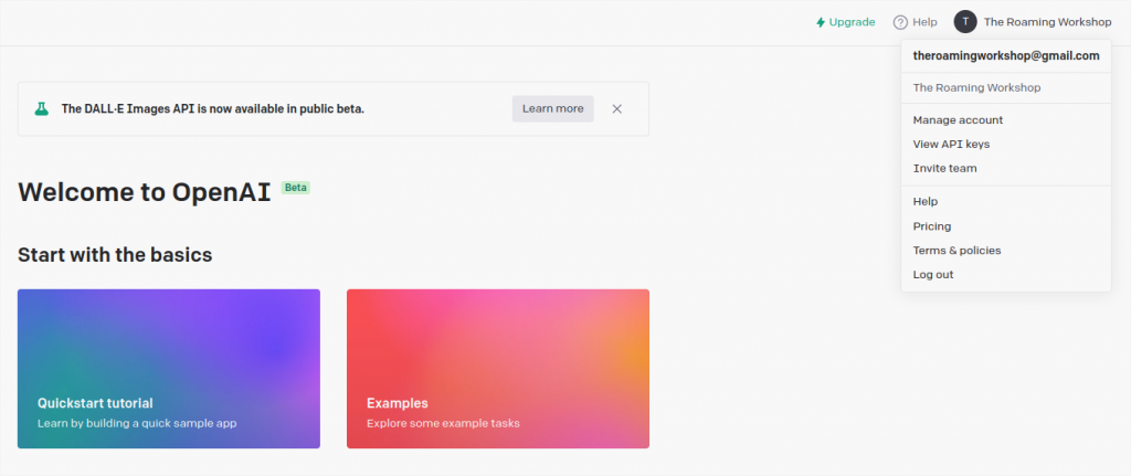
Sign up to use Dall·E 2 from their web site, pressing Sign Up button.
You'll have to verify your email address and then log into your account. Be careful because you'll be redirected to the commercial site https://labs.openai.com
Here we need to type our secret key in place of YOUR_API_KEY.
Also write a description for the image you want inside prompt.
With n we define the number of images generated by this request.
And size is the picture size, allowing 256x256, 512x512, o 1024x1024.
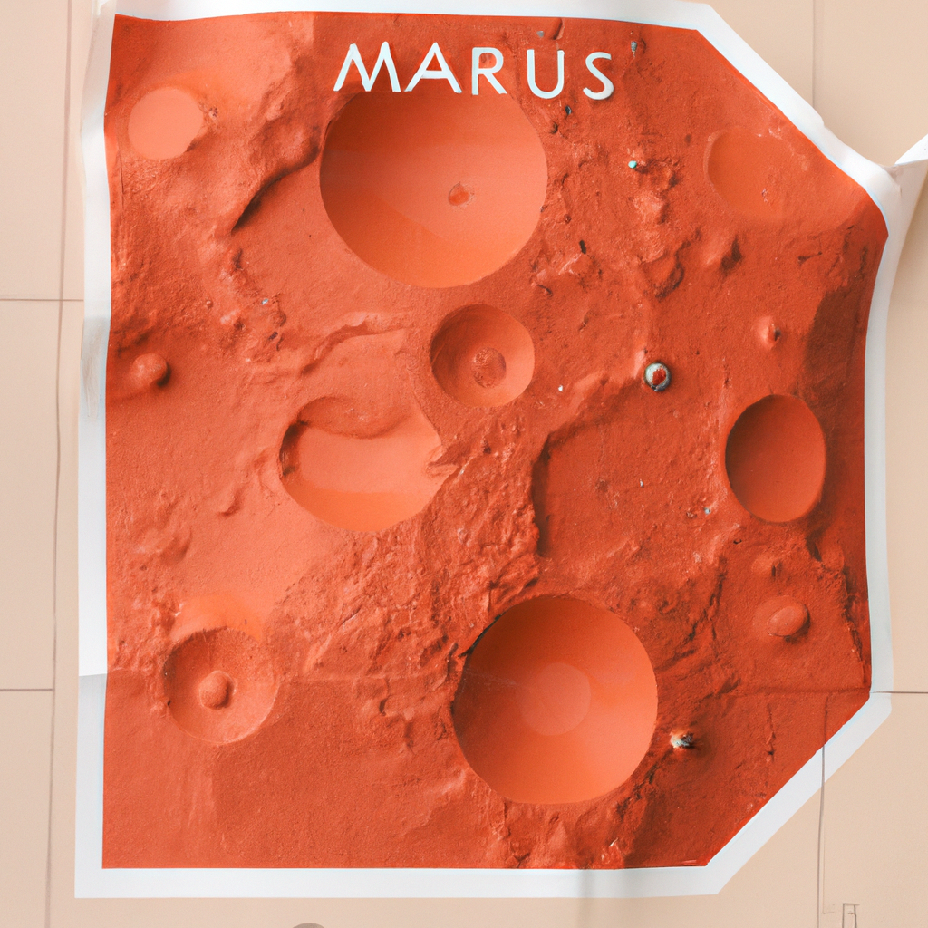
I'm going to try with "a map of Mars in paper".
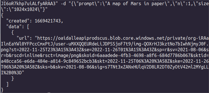
curl https://api.openai.com/v1/images/generations -H "Content-Type: application/json" -H "Authorization: Bearer sk-TuApiKeyAqui" -d "{\"prompt\":\"A map of Mars in paper\",\"n\":1,\"size\":\"1024x1024\"}"
TIP! Copy+paste this code in your terminal, replacing your secret key "sk-..." and the prompt.
You'll get back an URL as a response to your request, which is a web link to the generated image.
Open the link to see the result:
"A map of Mars in paper" with Dall·E 2. The Roaming WorkShop 2022.
Amazing!
Pricing
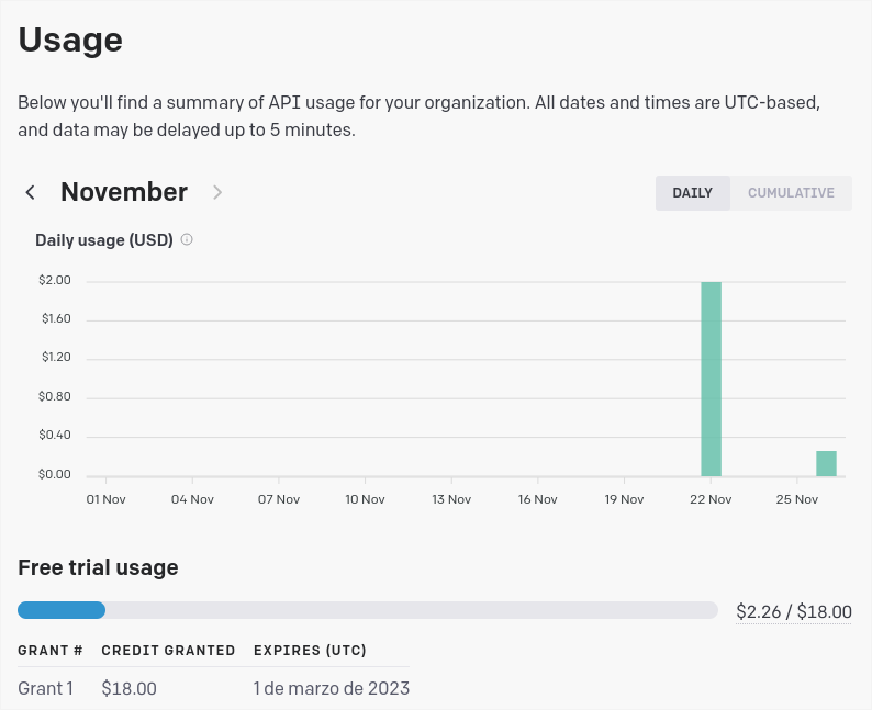
Well, well... let's get back to Earth. You wouldn't think this speed and quality would be free, would you? Go back to your OpenAI account where you can see the use that you make fo the API and how you spend your credit.
As I was saying earlier, the Beta offers 18$ to spend during 3 months and every picture in 1024px is about 0,065$ (0,002$ for lowest quality).
All the main AI platforms similar to OpenAI (Midjourney, Nightcafe, DreamAI, etc) work this way, offering some credit for use, as it is the powerful performance of their servers what is being traded.
Alternatives (free ones)
There are various open-source and totally free alternatives. I invite you to try them all and choose the one you like the most, but I must warn you that there are many software and hardware requisites. You specially need a good graphic card (or several of them). In the end, you need to put in the balance how much you'll use the AI, and if it's not worth spending a couple cents for a couple pictures every now and then.
From the 4 recommendations below I have successfully tested the last two, the least powerful of them:
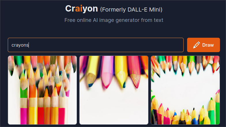
Looks promising for its simple installation and use. Don't trust the picture above (it's their pixelated module) because it has plenty of complex options for very detailed image generation.
There is also plenty documentation made by users and support via Discord.
On the other hand, they recommend about 16GB of VRAM (virtual RAM from the GPU of your graphic card). I crashed for insufficient memory without seeing the results...
Very technical and complex. The results look brilliant, but I couldn't achieve installation or web use. It uses several specific python modules that supposedly run on Google Colab. Or it's discontinued and it's currently broken, or the documentation is poor, or I'm a completely useless on this... Additionally the recommend about 21GB of VRAM to run standalone, although it could be shared using Colab... I could never check.
One of the many repositories derived from dalle-mini, in this case comes in a handy package that we can use freely with no cost in our home PC having very little hardware and software requirements. It runs as a local webapp in your browser as it generates a server that you can access anywhere in your network.
Together with Upscayl, they make good tandem to generate AI images in your own PC for free.
Gallery: Dall·E 2
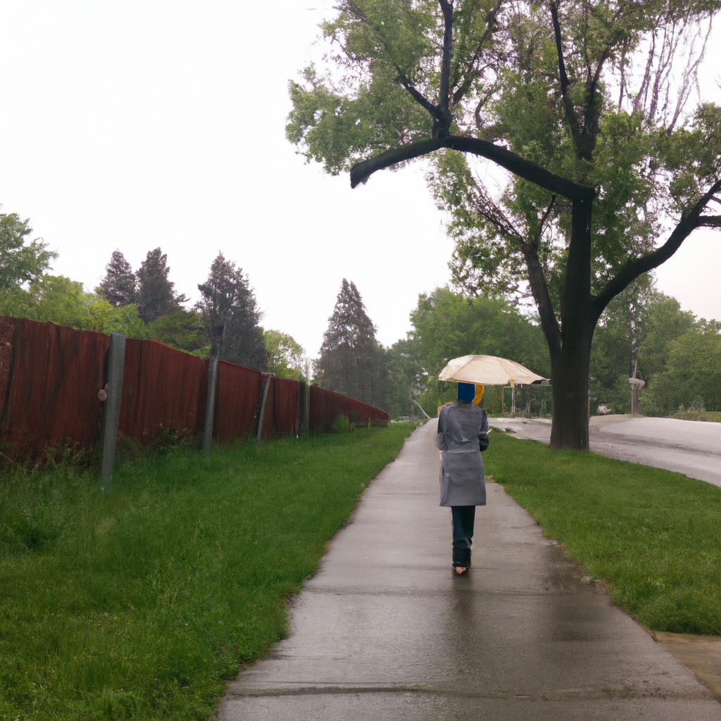
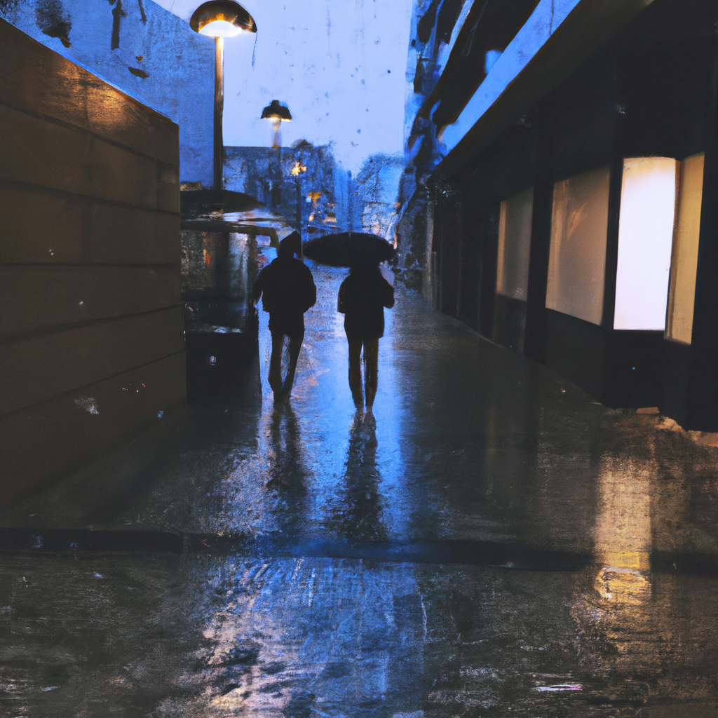
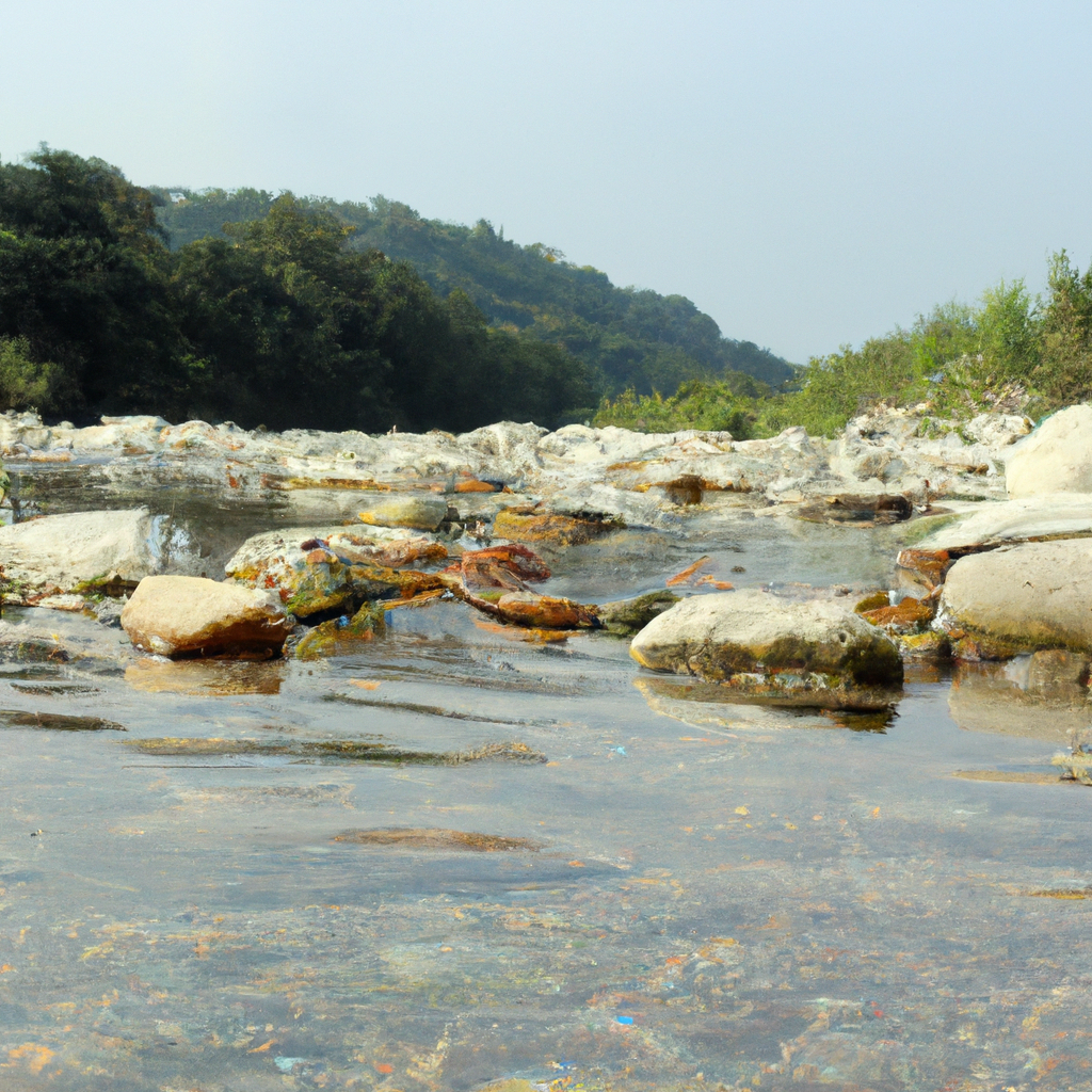
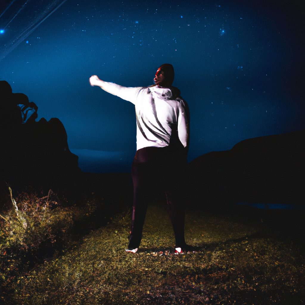
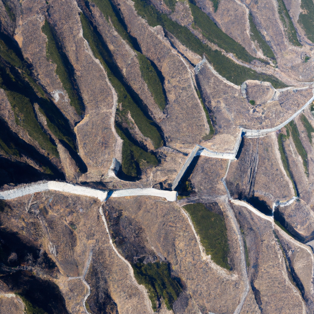
"A walk in the rain""A walk in the rain""A map of Mars in paper""River photograph""Show me some stars""Teide"Teide eruption" 1"Teide eruption" 2"The chinese wall seen from space"
I was writing a post where I wanted to insert a 3D model to picture it better, and I even thought in doing a viewer myself. But I didn’t have to browse long to find Three.js.
Let's keep with the example and fill up the second <script> block defining a scene with an animated rotating cube:
<script type="module">
        import * as THREE from 'three';
	const scene = new THREE.Scene();
	const camera = new THREE.PerspectiveCamera( 75, window.innerWidth / window.innerHeight, 0.1, 1000 );

	const renderer = new THREE.WebGLRenderer();
	renderer.setSize( window.innerWidth, window.innerHeight );
	document.body.appendChild( renderer.domElement );

	const geometry = new THREE.BoxGeometry( 1, 1, 1 );
	const material = new THREE.MeshBasicMaterial( { color: 0x00ff00 } );
	const cube = new THREE.Mesh( geometry, material );
	scene.add( cube );

	camera.position.z = 5;

	function animate() {
		requestAnimationFrame( animate );

		cube.rotation.x += 0.01;
		cube.rotation.y += 0.01;

		renderer.render( scene, camera );
	};

	animate();
</script>
All of this would look like this:
Add drag controls and background
Now we have a base to work with. We can add some functionality inserting the OrbitControls module.
//Import new modules at the beginning of the script
import { OrbitControls } from 'https://unpkg.com/[email protected]/examples/jsm/controls/OrbitControls.js';

//then add the mouse controls after declaring the camera and renderer
const controls = new OrbitControls( camera, renderer.domElement );
Also, you can modify the background easily, but you will need to host your images within your app in a server, or run it locally, because of CORS. I will be using the background image of the blog header, which was taken from Stellarium.
First define a texture. Then, add it to the scene:
//do this before rendering, while defining the scene
//define texture
const texture = new THREE.TextureLoader().load( "https://theroamingworkshop.cloud/demos/Unity1-north.png" );

//add texture to scene
scene.background=texture;
Full code:
<!DOCTYPE html>
<html>
	<head>
		<meta charset="utf-8">
		<title>My first three.js app</title>
		<style>
			body { margin: 0; }
		</style>
	</head>
	<body>
        <script async src="https://unpkg.com/[email protected]/dist/es-module-shims.js"></script>

        <script type="importmap">
          {
            "imports": {
              "three": "https://unpkg.com/[email protected]/build/three.module.js"
            }
          }
        </script>
<body style="margin: 0; width:100%;height:300px;">
        <script async src="https://unpkg.com/[email protected]/dist/es-module-shims.js"></script>

        <script type="importmap">
          {
            "imports": {
              "three": "https://unpkg.com/[email protected]/build/three.module.js"
            }
          }
        </script>

    <script type="module">

    import * as THREE from 'three';
	import { OrbitControls } from 'https://unpkg.com/[email protected]/examples/jsm/controls/OrbitControls.js';

	const scene = new THREE.Scene();

	const texture = new THREE.TextureLoader().load( "https://theroamingworkshop.cloud/demos/Unity1-north.png" );
	scene.background=texture;

    const camera = new THREE.PerspectiveCamera( 75, window.innerWidth / window.innerHeight, 0.1, 1000 );

	const renderer = new THREE.WebGLRenderer();
	renderer.setSize( window.innerWidth, window.innerHeight );
	document.body.appendChild( renderer.domElement );

    const controls = new OrbitControls( camera, renderer.domElement );

	const geometry = new THREE.BoxGeometry( 1, 1, 1 );
	const material = new THREE.MeshBasicMaterial( { color: 0x00ff00 } );
	const cube = new THREE.Mesh( geometry, material );
	scene.add( cube );

	camera.position.z = 5;

	function animate() {
		requestAnimationFrame( animate );

		cube.rotation.x += 0.01;
		cube.rotation.y += 0.01;

		renderer.render( scene, camera );
	};

	animate();
</script>
</body>
</html>
Insert a 3D model
Now let's replace the cube for our own 3D model which, in the case of Three.js, will be a glTF (.GLB o .GLTF) format, that is most supported and renders faster (.fbx, .stl, .obj and so on are also supported).
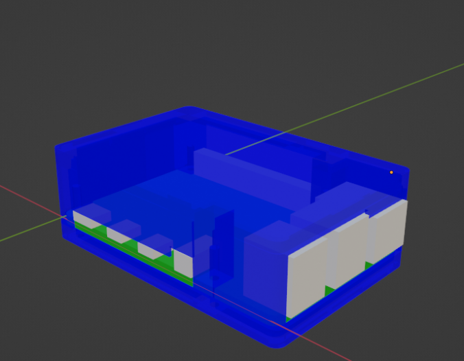
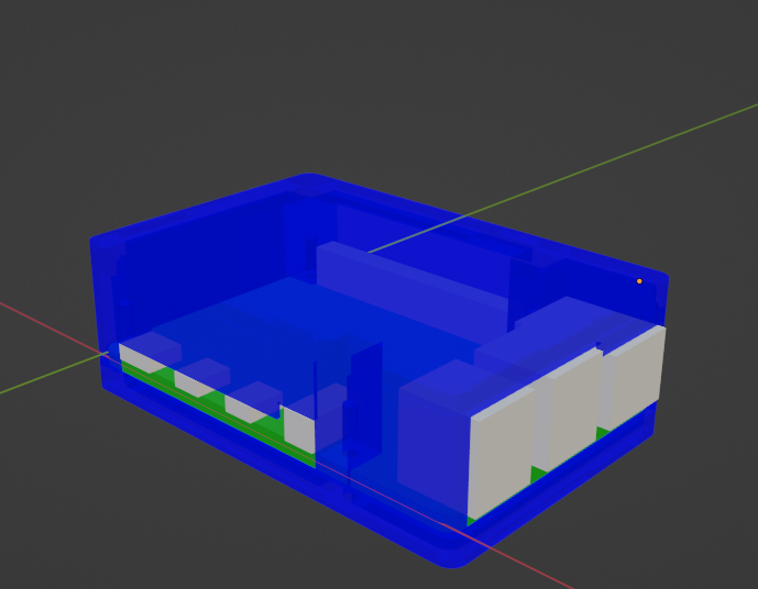
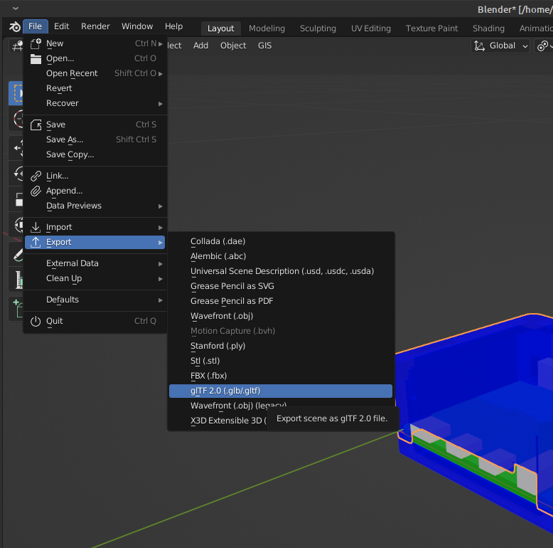
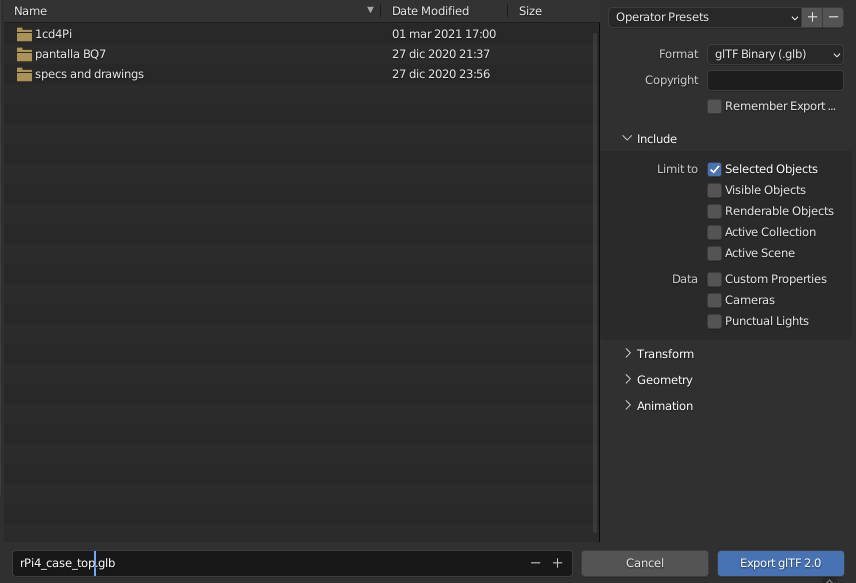
I will export a .glb of this basic Raspberry Pi 4B case that I did some time ago using Blender:
Now, replace the <script> block based on the "webgl_loader_gltf" which was shown at the start of the post: