tech explorers, welcome!

Tag: pcb

Raspberry Pi 5 fan setup in Ubuntu and status indicator

The heat arrived once again and I was feeling that my Raspberry Pi was too warm considering that it has the official built-in fan, with temperatures easily rising above 60ºC.

Since I installed Ubuntu on it, the fan didn’t seem to work right, but that’s something that has been solved in the recent versions of the kernel.

So here’s how you can set it up in Ubuntu and display it’s status.

Fan check

First of all let's check that our fan is working correctly by managing it manually.

Update your system so you can get the latest fixes that affect the fan. My latest version is Ubuntu Linux 24.04.2.

Now you should be able to turn on the fan manually by typing the following command in the terminal:

echo 4 | sudo tee /sys/class/thermal/cooling_device0/cur_state

A value of 4 will turn on the fan in it's maximum revolutions. You can change this value from 0 to 4.

If the above worked correctly you will hear significant noise from your fan. Now you can turn it off again by echoing a value of 0:

echo 0 | sudo tee /sys/class/thermal/cooling_device0/cur_state

So you see that altering the value in the cur_sate file manually changes the fan speed. That's exactly what the fan daemon does once it's configured, so we will monitor this value later to find out if our fan is working (returned value != 0):

cat /sys/class/thermal/cooling_device0/cur_state

Fan setup

The fan wasn't preconfigured in the earlier versions of the Ubuntu kernel for the Raspberry Pi. I'm not sure if it is now by default, but just check it by editing the config.txt file located in /boot/firmware and find out some lines similar to the following:

dtparam=fan_temp0=58000
dtparam=fan_temp0_hyst=10000
dtparam=fan_temp0_speed=200

If you cannot find them, just add them at the end of the file.

You may also adjust these values freely, considering:

fan_temp0=58000 indicates the trigger temperature that will turn on the fan

fan_temp0_hyst means the temperature reduction that turns off the fun (10000 below 58000 = 48000)

fan_temp0_speed indicates the fan speed, from 0 to 255

So that's our fan setup to run at 200rpm if the temperature is above 58ºC and turn off if it reduces 10ºC (~48ºC).

Now apply these changes by rebooting the system.

Fan monitoring

I was already monitoring a series of variables from my Raspberry Pi 5 using an OLED screen, as it's explained in this other post:

https://theroamingworkshop.cloud/b/en/2655/case-oled-display-for-raspberry-pi-with-status-panel/

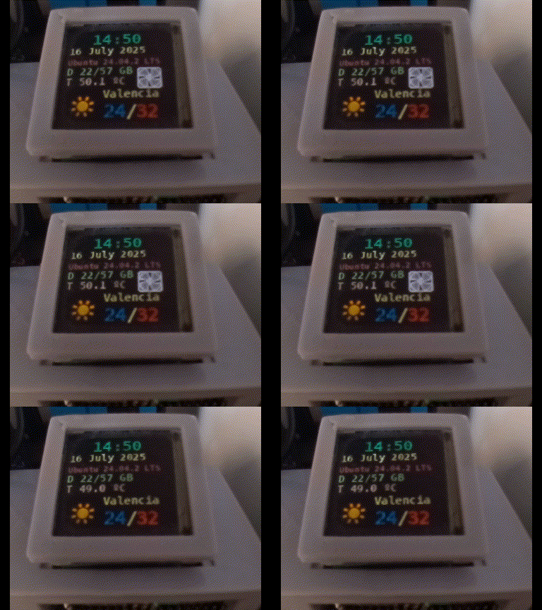
Let's now add an indicator with the status of the fan!

I've included a couple of lines to the python script to retreive the fan status executing the command that we saw above:

#Fan ON/OFF
cmd = "cat /sys/class/thermal/cooling_device0/cur_state"
Fan = subprocess.check_output(cmd, shell=True).decode("utf-8")

Somewhere below I am reading a .png file for the fan:

fan_img=Image.open("~/Documents/OLED/fan-icon.png")
fan_img = fan_img.resize((30, 30), Image.BICUBIC)
fan-icon.png

And right at the display stage, I would show it if the value of Fan is different to cero (fan is ON):

if int(Fan)!=0:
    bg.paste(fan_img,(90,55))

All these changes have been updated in the Github repository for my previous display script:

https://github.com/TheRoam/RaspberryPi-SSD1351-OLED

So that's a very nice looking fan indicator for your display!

See you next time!👋

🐦 @RoamingWorkshop

Case + OLED display for Raspberry Pi with status panel

I was tempted to just switch cases from my Raspberry Pi 4 to the Raspberry Pi 5, but look at it…

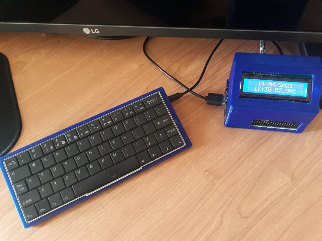
  • 16×2 LCD display from an Arduino Starter Kit
  • C++ program with the WiringPi library
  • DIY case

I was really proud of it at the time and it was good learning back in 2020, but surely I could do better. Surely I could do a cool status panel!!

Components

  • Raspberry Pi (probably compatible with any of them)
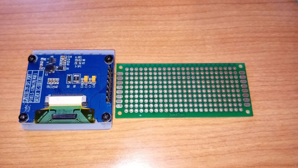
  • OLED display (RGB 1.5 inch size is ideal)
  • PCB prototype board
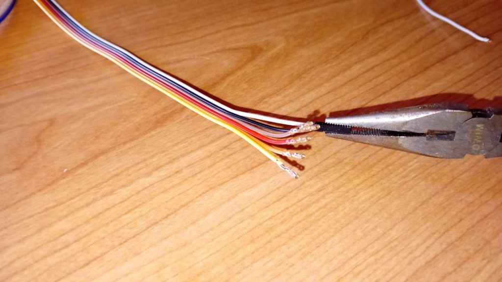
  • Jumper cables
  • Soldering iron
(courtesy of epiCRealism model in ComfyUI)
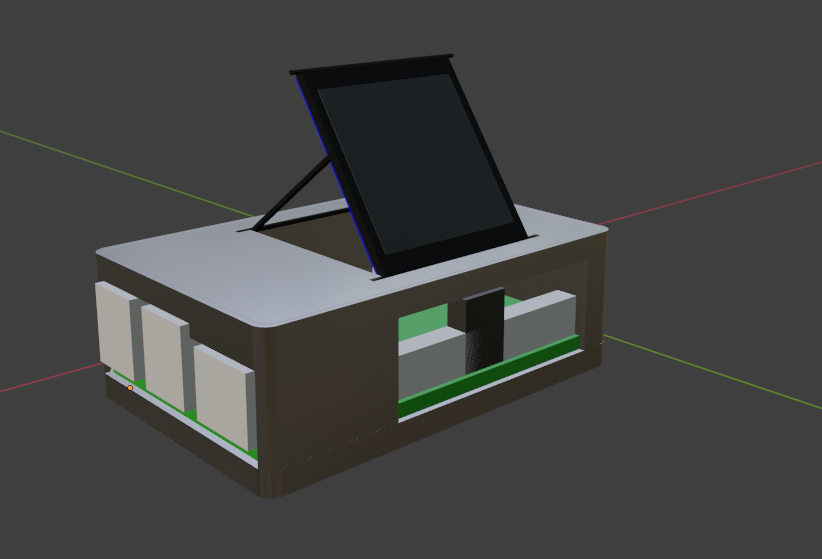
  • Casing (3D printed or handcrafted)

Software config

I'll configure the Raspberry to interact with this display using python, with the Adafruit Circuitpython library for the SSD1351 display controller:
https://learn.adafruit.com/adafruit-1-5-color-oled-breakout-board/python-wiring-and-setup#setup-3042417

It's as simple as installing Circuitpython with the following command:

sudo pip3 install --upgrade click setuptools adafruit-python-shell build adafruit-circuitpython-rgb-display

If you find issues with your python version not finding a compatible circuit python version, include --break-system-packages at the end. (It wont break anything today, but don't get used to it...)

sudo pip3 install --upgrade click setuptools adafruit-python-shell build adafruit-circuitpython-rgb-display --break-system-packages

Wiring

Now wire your display according to the manufacturer guidance. Mine is this one from BuyDisplay:

https://www.buydisplay.com/full-color-1-5-inch-arduino-raspberry-pi-oled-display-module-128x128

OLED DisplayRaspberry Pi (pin #)
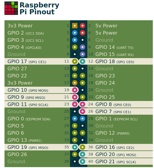
GNDGND (20)
VCC3V3 (17)
SCLSPI0 SCLK (23)
SDASPI0 MOSI (19)
RESGPIO25 (22)
DCGPIO 24 (18)
CSSPI0 CE0 (24)

Use a site like pinout.xyz to find a suitable wiring configuration.

You're ready to do some tests before making your final move to the PCB.

Script config

You can try Adafruit's demo script. Just make sure that you choose the right display and update any changes to the ping assignment (use IO numbers/names rather than physical pin numbers):

# Configuration for CS and DC pins (adjust to your wiring):
cs_pin = digitalio.DigitalInOut(board.CE0)
dc_pin = digitalio.DigitalInOut(board.D24)
reset_pin = digitalio.DigitalInOut(board.D25)

# Setup SPI bus using hardware SPI:
spi = board.SPI()

disp = ssd1351.SSD1351(spi, rotation=270,                         # 1.5" SSD1351
    cs=cs_pin,
    dc=dc_pin,
    rst=reset_pin,
    baudrate=BAUDRATE
)

Assembly

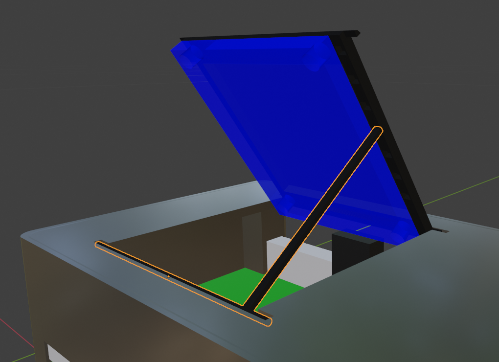
Here are the STL 3D files for this case design:

Now let's put it all together:

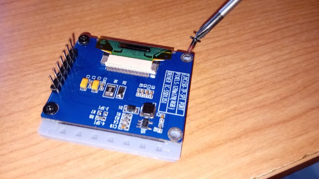
  1. Screw the frame to the display
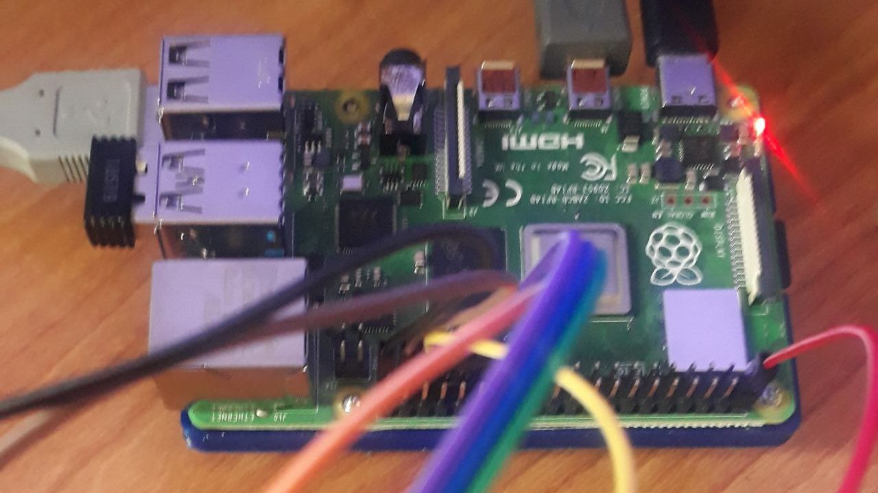
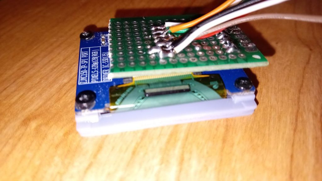
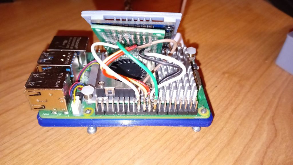
  2. Solder the 7 pins of the display to 7 jumper cables across the PCB
  3. Wire all connections to the Raspberry Pi
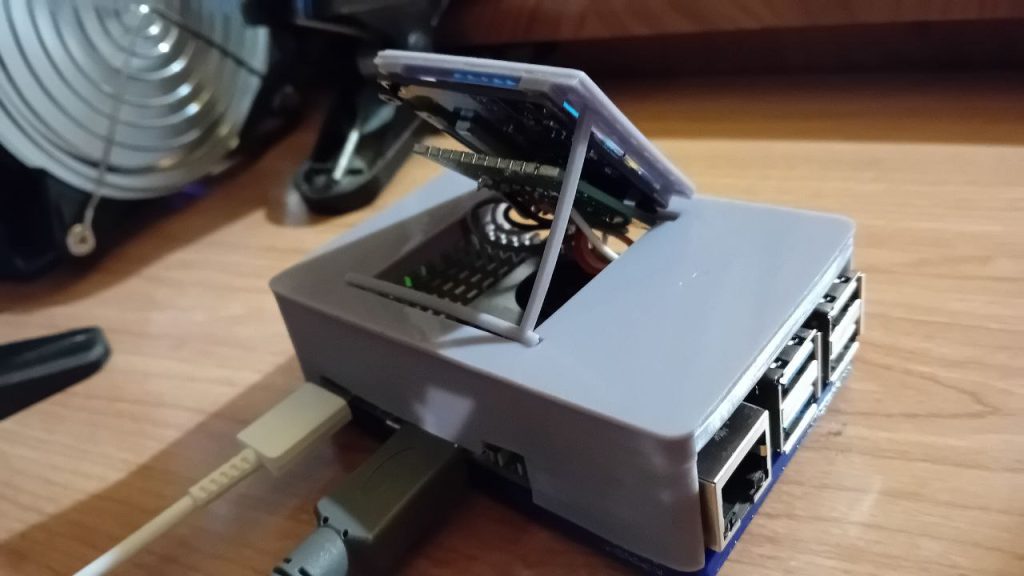
  4. Screw the top and bottom pieces together
  5. Place the display on the support

Final result

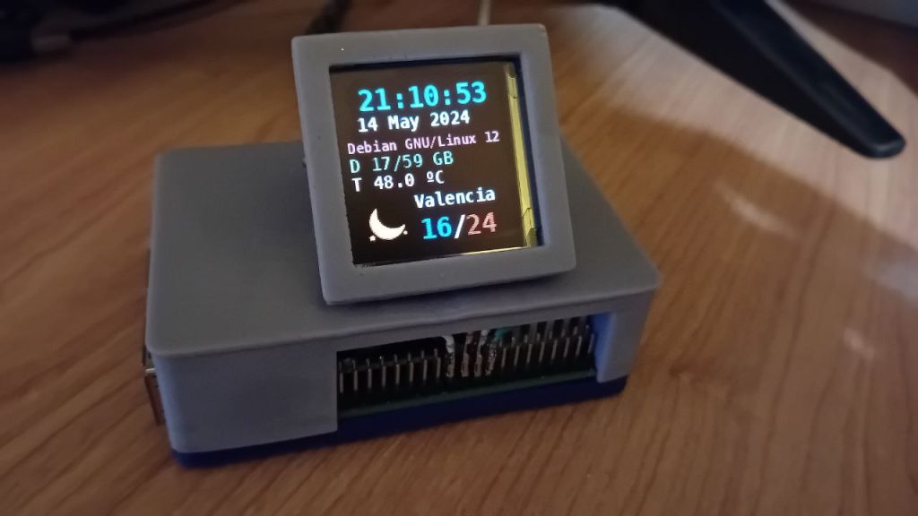
I've shared the script you see on the images via github:

https://github.com/TheRoam/RaspberryPi-SSD1351-OLED

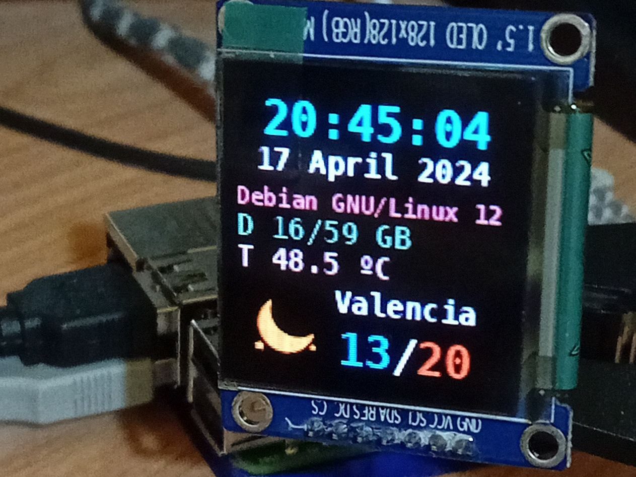
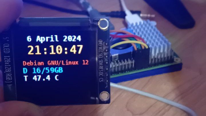
It currently displays:

  • Time and date
  • System stats (OS, disk usage and CPU temperature)
  • Local weather from World Meteorological Organization (updated hourly)

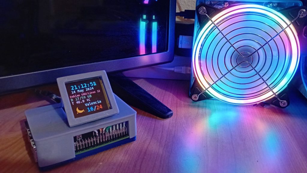
And this is how it ends up looking. Much better right?

As always, enjoy your tinkering, and let me know any comments or issues on Twitter!

🐦 @RoamingWorkshop