After lots of comings and goings, trials, redesigns, burnts, cuts and some minor explosions, finally I can bring a smart desktop clock I have been working on for the last 2 years. Making a detailed tutorial can be even longer and tedious, so I hope these traces can help make your own. I warn you this takes a lot of time and practice, and can’t be done carelessly…
Content
What's Temps-i 7?
Let's break down its name:
Temps mean time in the Valencia dialect,
i for internet, where it gets the time,
7 for the display, which uses 7 segments for every digit.
These three concepts define this compact desktop clock, with WIFI connectivity, temperature sensor and good autonomy.
Let's see how it's made!
Components
First, let's see the recipe ingredients and what each one does:
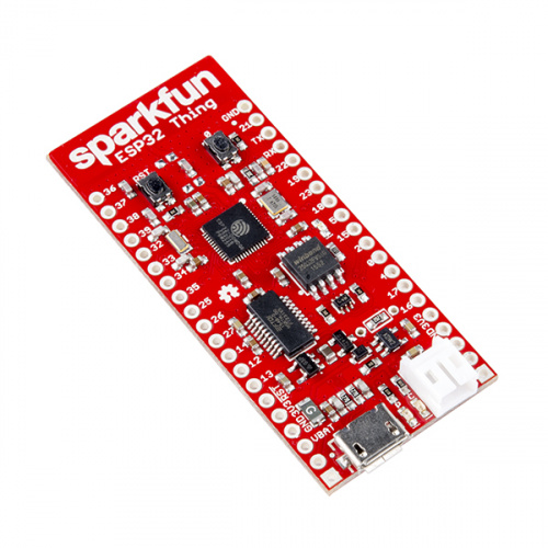
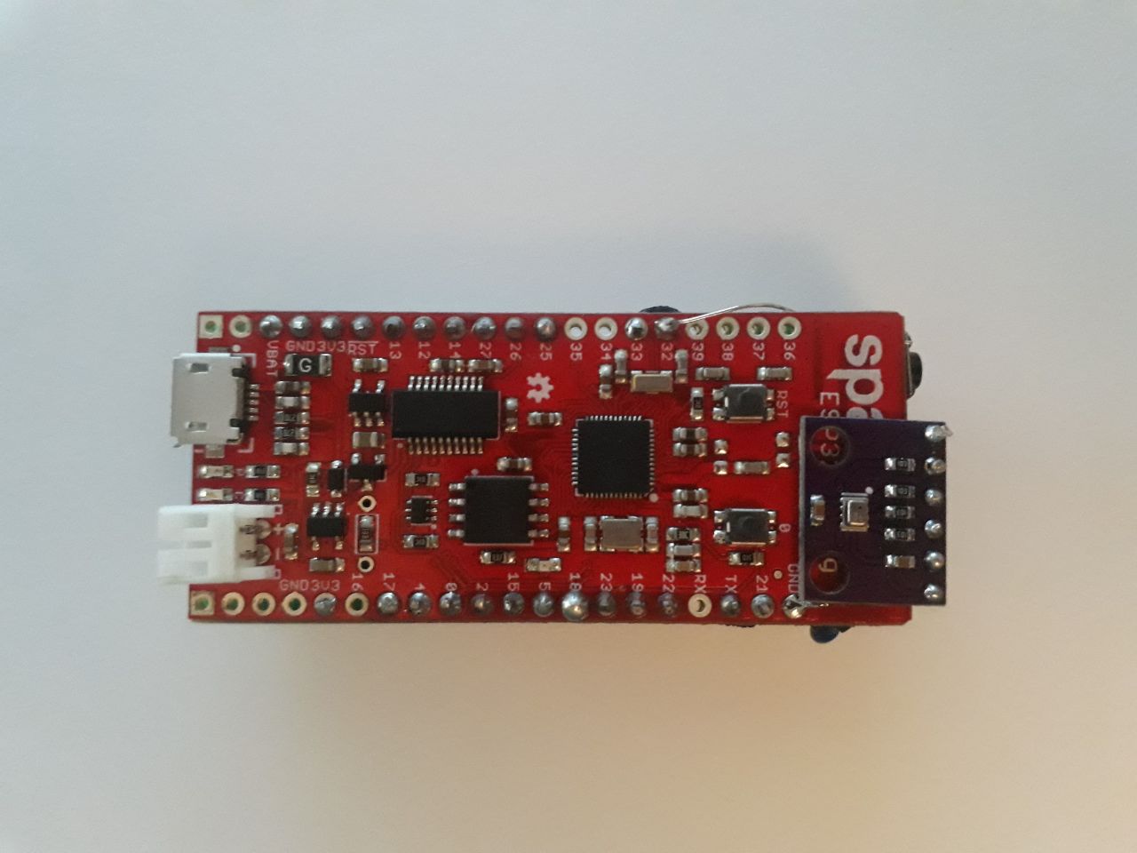
Sparkfun ESP32-Thing board >>Top performance microcontroller with WIFI and Bluetooth connectivity thanks to the ESP32 integrated chip, ideal for IoT projects.
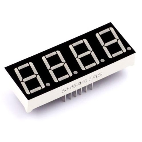
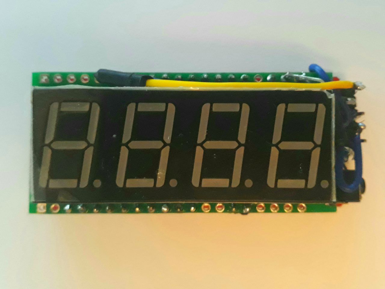
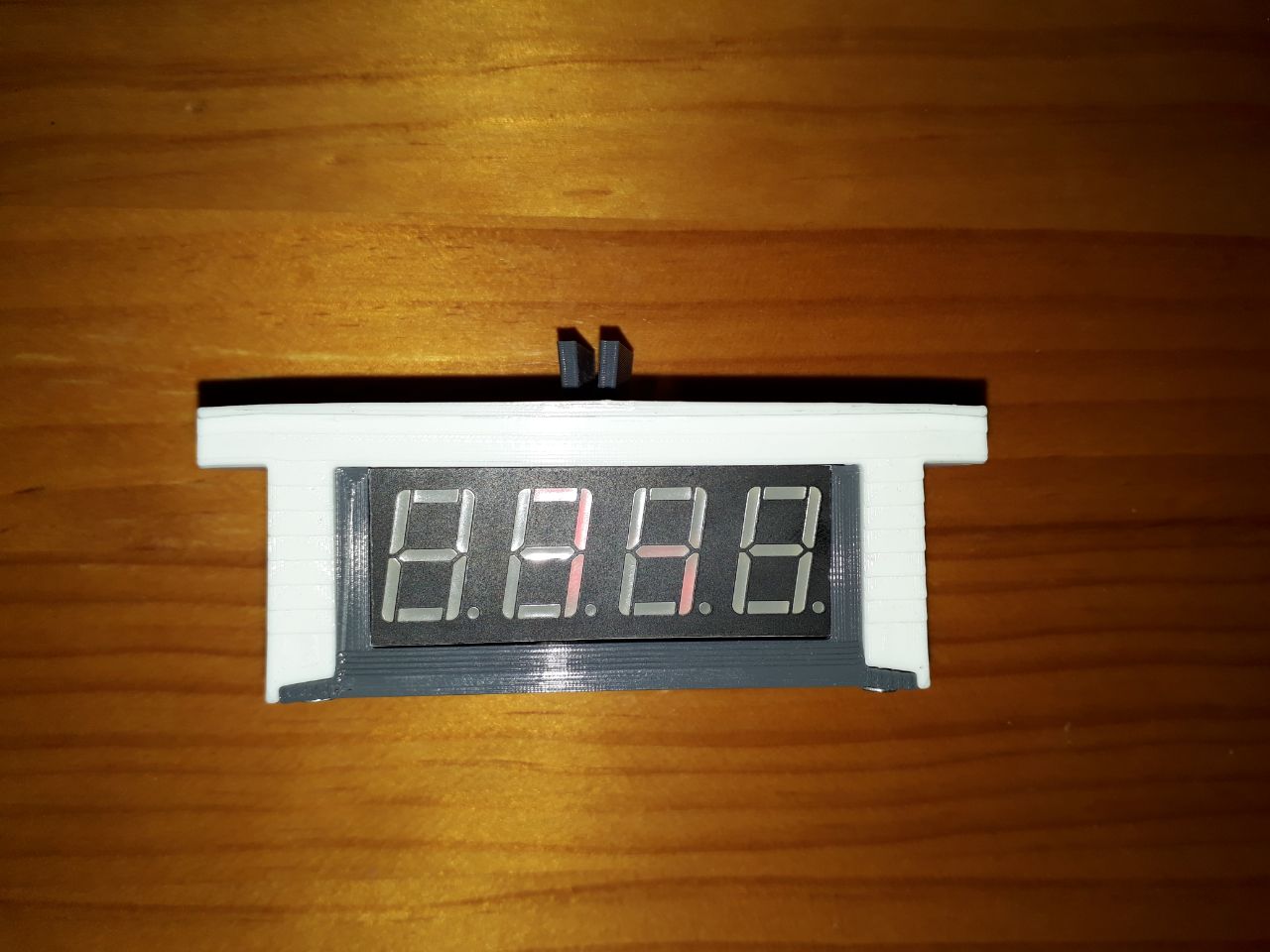
4 digits 7 segments red color display. >>Shows time and temperature.
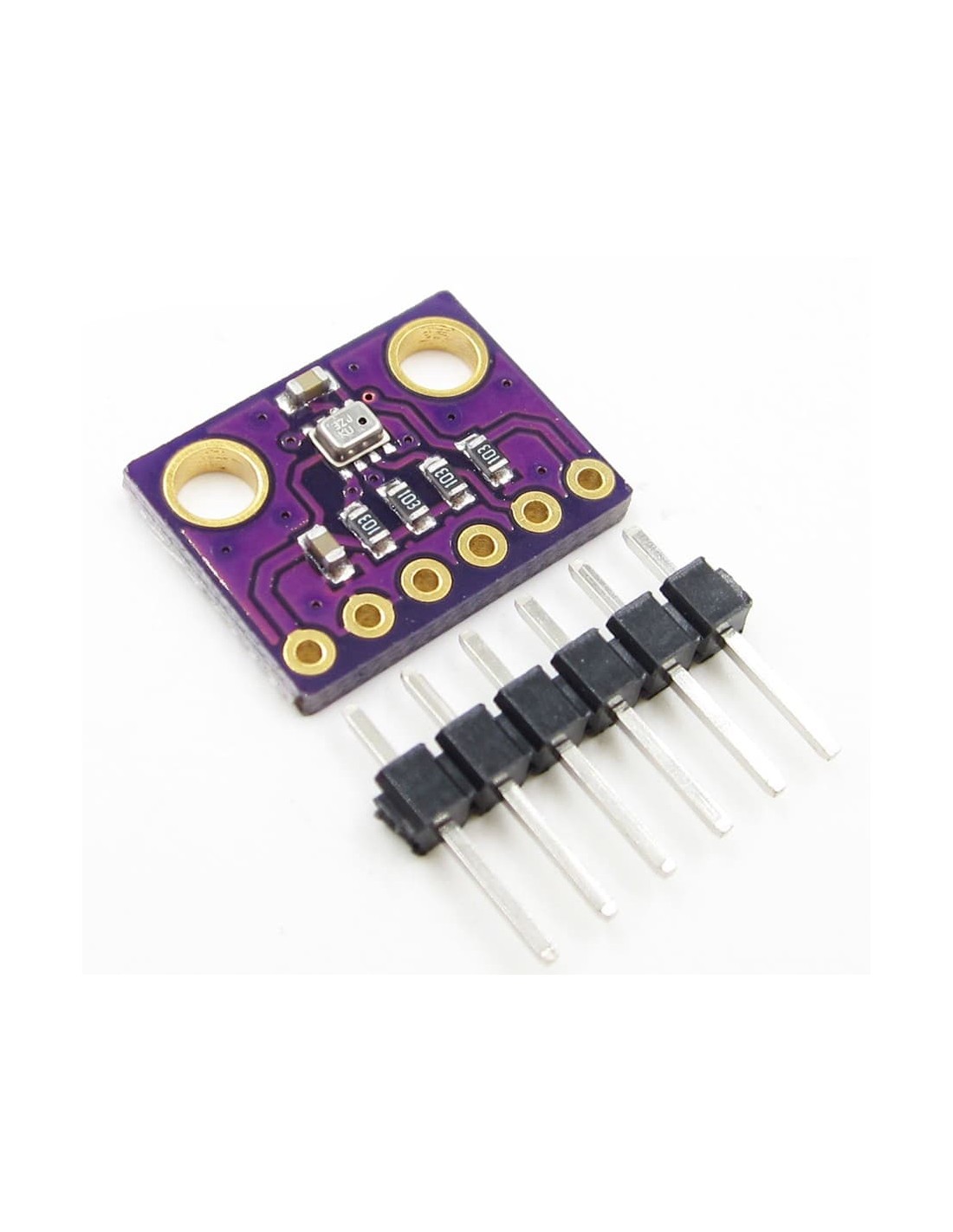
BMP-280 module. >>Temperature and barometric pressure compact digital sensor.
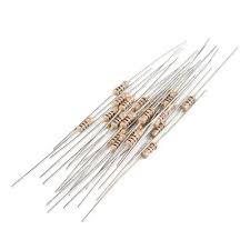
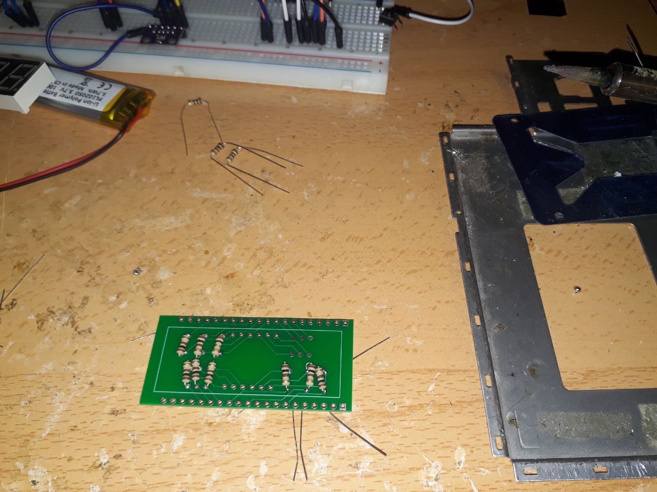
100 Ohm resistors >>Needed to reduce display current, without lowering brightness excessively (admits up to 1k Ohm, but leds would be hardly visible with daylight).
PCB with custom circuit. >>Simplifies display and resistors connectiont to the microcontroller.
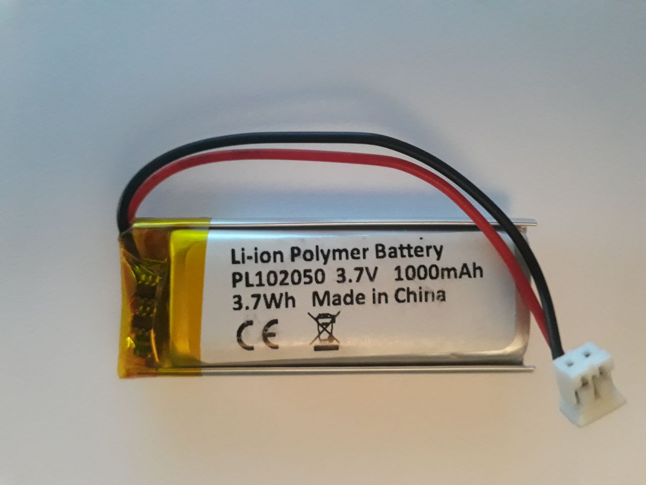
1000mAh 3.7v LiPo battery >>Ensures an autonomy up to 48 hours without external voltage.
Jumper cables. >>For additional connections of external modules.
Push button >>Used to switch the program on display.
Electronic design
It's very important to study the electronic components being used, read all the specifications and prototype with all precautions before we start soldering like crazy.
Component selection
The components listed earlier are not a mere coincidence or copied from elsewhere. They're the most successful trial of many others and meets the project needs:
The 4 digit display shows exactly what I'm after: the time. If I can also use it to show temperature, that's fine. But a better quality display, like LCD, would be unnecessarily demanding, and autonomy is another key requirement.
The microcontroller includes internet connectivity, as well as enough computing capacity. It also has sufficient in/out pins to control the display without a gpio expansor. Some other options I've tried:
More compact microcontrollers: Teensy 4, Digispark, SparkFun Pro Micro. They need a GPIO expansor (like PCF8574) and/or a WIFI module (like ESP-01). This also involves too many more connections.
Microcontrollers integrating WIFI and sufficient I/O, like NodeMCU ESP8266. Got out-dated and lacks processing capacity as the counter delayed almost 4 seconds every minute.
Prototyping electronic circuit
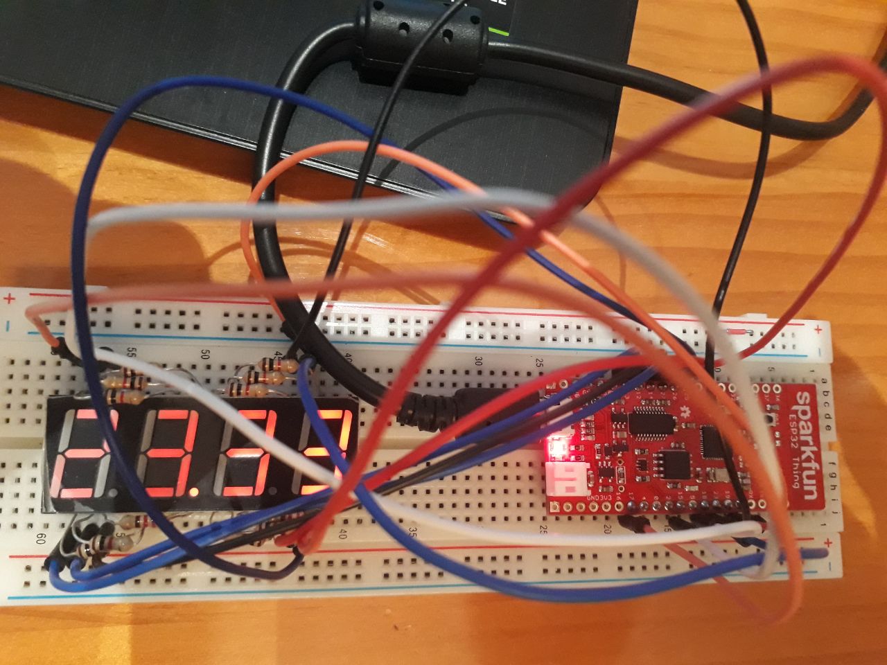
Having researched and obtained the components, connect them in a prototype board (protoboard) to test their operation.
In my case, after different pin combinations, the most organised way is the following:
ESP32-Thing
Component
VBAT
LiPo +
3V3
BMP-280 3V3
GND
LiPo - BMP GND BMP SD0 Push -
GPIO21
BMP SDA
GPIO04
BMP SCL
GPIO32
Push +
GPIO17
Display Digit 1
GPIO23
Display Digit 2
GPIO19
Display Digit 3
GPIO25
Display Digit 4
GPIO15
Display Segment A
GPIO22
Display Segment B
GPIO27
Display Segment C
GPIO12
Display Segment D
GPIO13
Display Segment E
GPIO18
Display Segment F
GPIO26
Display Segment G
GPIO14
Display Segment P (dot)
Pinout schematic
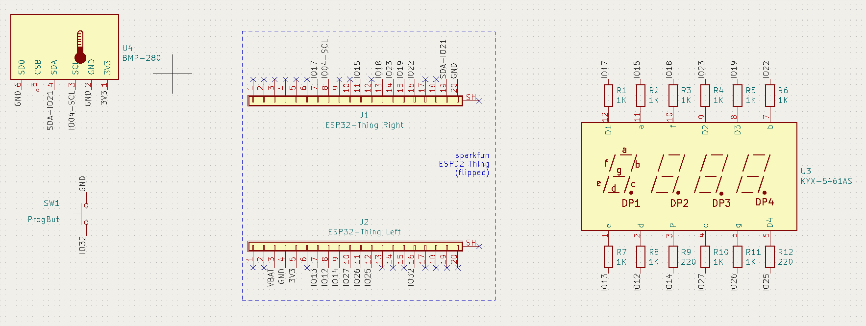
Once the prototype is achieved, you should save it in a schematic diagram using EDA software (electronic design automation) like Kicad, where you can also generate a PCB design that can be sent for manufacturing. Otherwise, you can always save the schematic in paper, as you wont remember where every cable was going in a couple months time...
Kicad is a bit tricky and it's good to practice with simpler projects. Despite this, it's quite manageable for medium users as it basically consists of searching and choosing symbols for our components and connect their pins accordingly to specifications.
To avoid messing the sketch up with cables, I used names in every connection, which is also valid in Kicad. Also, you'll see that the ESP32-Thing is made up of two 20x pin headers, as I didn't find a working symbol and didn't have time to design one properly. What really matters is that the design is working and coherent with reality.
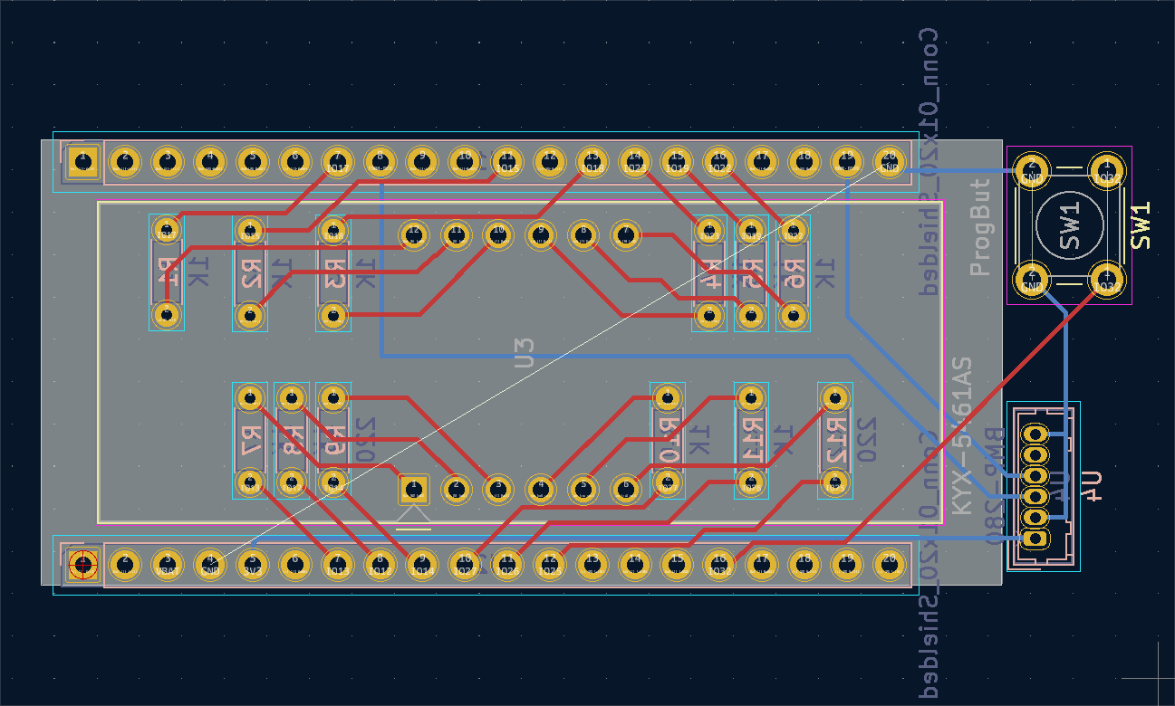
Kicad shematic
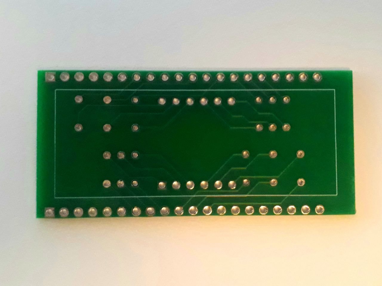
Next step is to assign footprints that are realistic for each symbol, so then we can design a printed circuit board that we can order (usually in China) for 15€ / 5 boards.
You don't need to go crazy on this, specially if you're not experienced. I only need to make soldering connections simpler, as in this case you need about 90 of them but keeping a compact design.
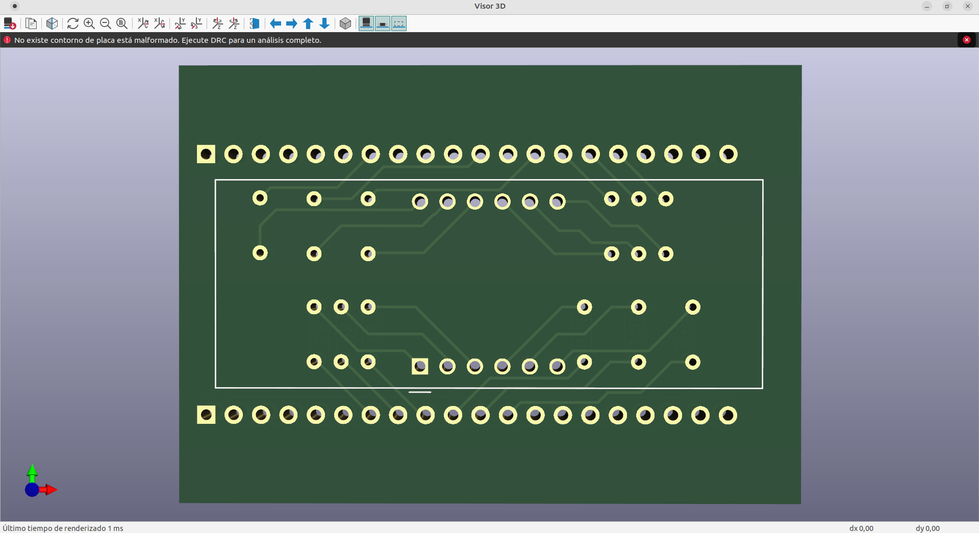
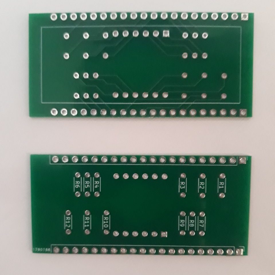
PCB design in KicadPCB 3D viewerOrdered PCBs
Clock programming
Most microcontrollers, like the ESP32-Thing, are compatible with the Arduino IDE, which makes it simpler to connect the board to a PC and load a clock program.
Before starting, it's important to make a list of tasks and functions that we want to include in the program and modify it as we code. This way you can try different functions separately and debug every step to find errors quickly. In my case, and after many trials, the program will consist of the following:
Define libraries and variables.
Configure pins.
Connect WiFi.
Get date via SNTP.
Disconnect and turn off WiFi (saves battery).
Convert date into digits.
Show digits on display.
Start timer.
Start reading program change pin.
Change program on pushbutton activation.
Read sensors.
Show temperature on display.
Update time after timer ending (every minute).
Restart timer.
I don't want to spend too long on the code, and it's also not the most tidy I have, but here it is for anyone who wants to copy it, and also on github:
Notice you'll need these additional libraries installed using the Arduino IDE:
esp32 board manager by Espressif
WiFiMulti library
Adafruit_BMP280 library
(the rest of the libraries derive from these ones)
You should constantly try the performance of the code during prototyping so you can change any pin assignment in case of any malfunctioning. If it's all soldered and something fails, it will be really hard to find and solve the error, if it's from a connection.
Assembly
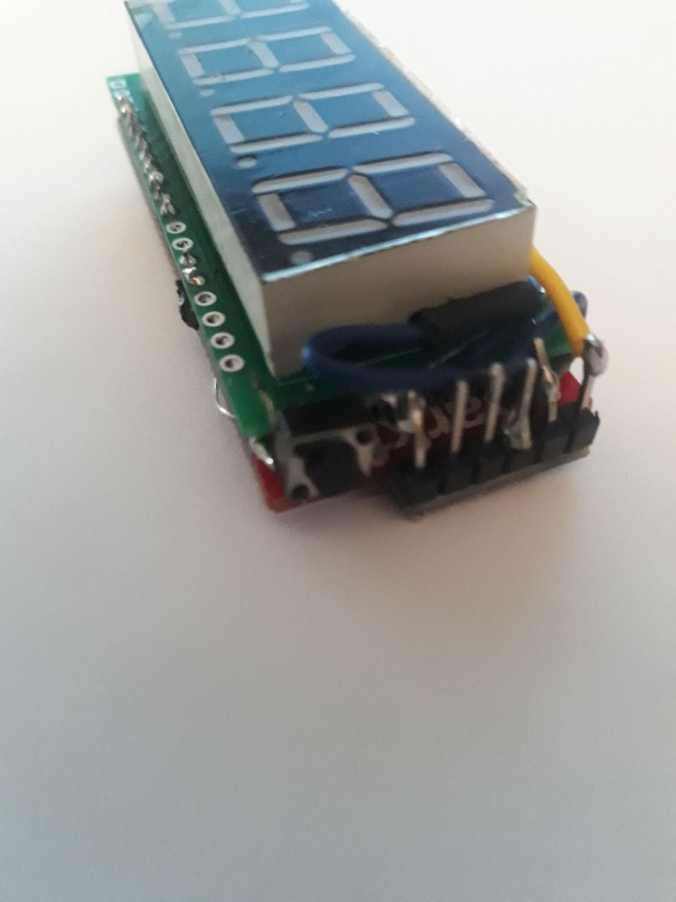
Soldering
Once the code is checked and the PCB is designed, you can start soldering with caution, as a wrong movement can damage your modules or produce errors in the program.
BMP-280 soldered to boardEsp32-Thing soldered to boardDisplay soldered to boardResistors soldered to board
Case design
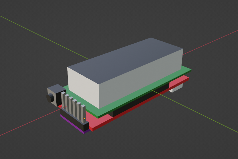
Having it all soldered you'll have a better idea of the final volume of the device. I measure it all with precision using a digital caliper to make a 3D model of it.
Blender 3D model of all components in their final position
This way you can now design a case around the model so you can craft it using a 3D printer. You could also use other types of assembling materials like plywood or metal.
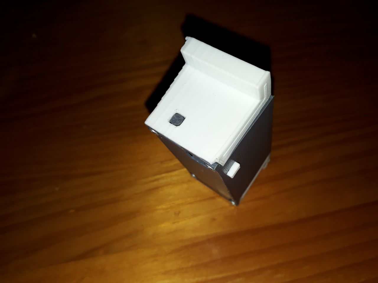
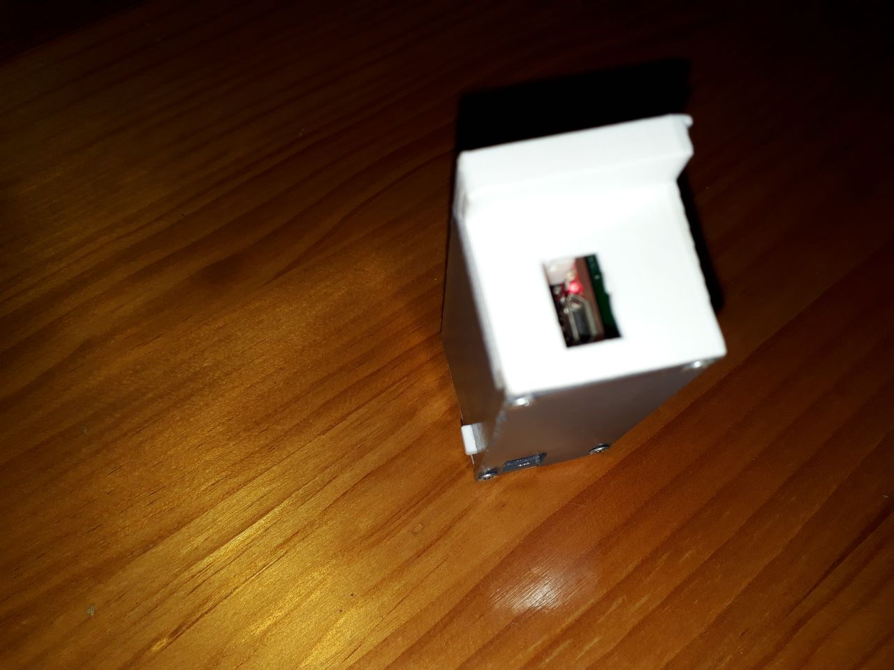
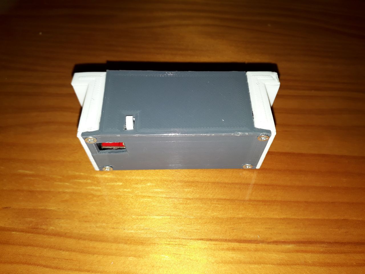
I usually craft two pieces (one as a base and another one as a cover) so they can be screwed together. I also include different voids to allow for the connection of the USB cable, to add the program switch button and to add a rotary support to hold the clock in a slot in the television.
I will also use white PLA in one piece and grey in the other to bring more life to the design, ending it all like this:
And that's it. I hope you liked it and find it useful. Now you can get your own WIFI clock crafted! Any doubt about this clock can be dropped on Twitter! 🐦