One of the ways to avoid roomy buttons in your Arduino projects is using boards or modules with tactile pins, like some ESP32 modules.
Despite this, the majority of the boards do not include this feature, but reading this entry in esp32.com forum y found something interesting:
https://www.esp32.com/viewtopic.php?t=23066
With a quick calibration you can use any analog pin as a tactile sensor. Despite there are a few libraries about this, you really just need a couple of function, so let’s get on with it!
Components
For this project I am using these simple components:
- 1x SparkFun Pro Micro board with ATmega32u4
In fact, it's a cheap clone from Aliexpress.
https://learn.sparkfun.com/tutorials/pro-micro--fio-v3-hookup-guide/hardware-overview-pro-micro - 1x Micro USB data cable.
- 1x LED diode.
- 1x 1K or 220 Ohm resistance.
- 3x Jumper cables
- 1x Protoboard
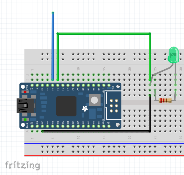
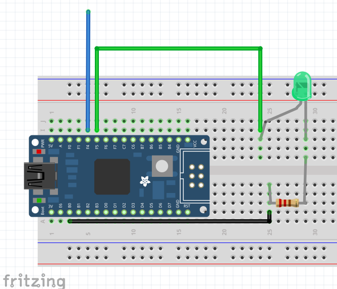
Wiring
If using the Pro Micro, this is the pin assignment:
| Pro Micro | Componente |
|---|---|
| Puerto Micro USB | Cable USB |
| Pin 21 (A3) | Cable puente desconectado |
| Pin 20 | LED+ |
| GND | Resistencia |
All you need to take into account is to connect the juper wire, that we will use as tactile sensor, into an analog pin.
Arduino sketch
You'll find a ready to use Arduino sketch in my github:
https://github.com/TheRoam/TRW_AnalogTouch/blob/main/ProMicro_Blink_AnalogTouch.ino
It states "ProMicro" but it can really be used with any compatible microcontroller board. You just need to select your board in the board manager.
The Pro Micro runs a ATMega32u4, which is compatible with the Arduino Leonardo board.
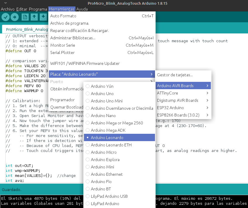
With this config, compile the script and upload to the board.
Result
Open the Serial Monitor, which should show blank as the debugging text is set to minimum by default.
Now we touch the free pin of the jumper wire and see how the led lights, and how the "touch" is detected in the Serial Monitor.
You'll also see that the script accumulates "touches" so this can be used in other programs.
The code
Briefly this is what the program does:
- During
setup(), start serial communication, activate led pin and fill-up the analog readings array withsetTouch(Reads 20 values by default).
void setup() {
  // initialize serial communication at 115200 bits per second:
  Serial.begin(115200);
  //enable LED pin
  pinMode(LP,OUTPUT);
  setTouch(TP);
}- Next we run the
loop()function, where the readings are updated at the start of each loop.
setTouch(TP);
//------loop continues------//
void setTouch(int tp){
  //fill up the array
  for(int a=0;a<VALUES;a++){
    mean[a]=analogRead(tp);
    delay(10);
  }
}- Check if debugging is minimal or extended, and run the main function (the only difference is the amount of debugging messages).
//run check
  if(out==1){
    extended(TP);
  }else if(out==0){
    minimal(TP);
}- Then, the main function:
- Runs through the reading array,
- Obtains the mean value,
- Gets a new reading,
- Calculates the difference between new reading and average,
- If the difference is bigger than the REFV voltage drop value: "touch" is identified, it's printed in Serial Monitor, touch counter is increased and led is lit.
- Restore average to 0, turn led off and return "touch" variable.
int minimal(int tp){
  //start reading values
  for(int i=0;i<VALUES;i++){
    //get average of array
    for(int j=0;j<VALUES;j++){
      avg+=mean[j];
    }

    avg=avg/VALUES;

    //read current value
    fin=analogRead(tp);

    //compare average with current value
    if((avg-fin)>REFV){
      Serial.println("----------  T   O    U    C    H  ----------");
      //increase counter
      touch++;
      //print touch count
      Serial.print("T: ");
      Serial.println(touch);
      //light led
      ledON(LP);
      //wait 1 second after touch detected
      delay(1000);
    }
    //restart counter
    avg=0;
    //restart led
    ledOFF(LP);
    delay(VALINTERVAL);
  }
  return touch;
}- After this the loop is restarted, going back to point 2.
Other configurations
The script includes different configuration variables that we find under the '#define's:
OUT: defines the amount of debugging text. Value 0: minimal; Value 1: extended.VALUES: analog readings array size.TOUCHPIN: define the analog pin number used for touch.LEDPIN: define the pin number used for led.VALINTERVAL: evaluation interval in milliseconds.REFV: voltage drop value (in millivolts) which identifies a "touch".
// OUTPUT verbosity
// 1: extended --> Prints ADC array, mean value, touch count and touch message with touch count
// 0: minimal  --> Prints touch message with touch count

#define OUT 0

// comparison variables
#define VALUES 20       //values for mean array
#define TOUCHPIN 3      //touch pin
#define LEDPIN 20       //led pin
#define VALINTERVAL 100 //evaluation interval
#define REFV 80         //reference voltage drop in mV
Calibration
Changing the configuration you can calibrate the script for different boards. From what I've tested, this is a good sequence:
- Set a high REFV, for example 100.
- Run the extended script with OUT 1
- Open Serial Monitor and have a look at the average values for a while (e.g.: 230)
- Now touch the jumper wire and see what the values are now (e.g.: 170)
- Make the difference between the average at 3. and the average at 4 (230-170=60).
- Set your REFV to this value (60) and play around it.
- For more sensitivity, set it a bit lower (50)
- If there is detection with no touch, increase it (80)
- Because of CPU load, REFV value can vary if OUT 1 or OUT 0
Found it useful? Any doubts? Leave your comment on 🐦 Twitter!
