Después de muchas idas y venidas, pruebas, rediseños, quemaduras, cortes y alguna que otra pequeña explosión, por fin traigo un del reloj de mesa inteligente en el que llevo dos años trabajando. Hacer un tutorial completo y detallado sería todavía más largo y tedioso, pero espero que estas pinceladas sean de ayuda para hacer el tuyo propio. Aviso de que se requiere mucho tiempo y práctica y no se puede hacer a la ligera…

Qué es Temps-i 7?

Desgranemos su nombre:

  • Temps es tiempo en valenciano,
  • i de internet, que es de donde obtiene la hora,
  • 7 de la pantalla que utiliza, de 7 segmentos para cada dígito.

Estos tres conceptos definen a este compacto reloj de sobremesa, con conectividad WIFI, sensor de temperatura y buena autonomía.

Vamos a ver cómo se hace!

Componentes

Primero, veamos los ingredientes de la receta y qué hace cada uno:

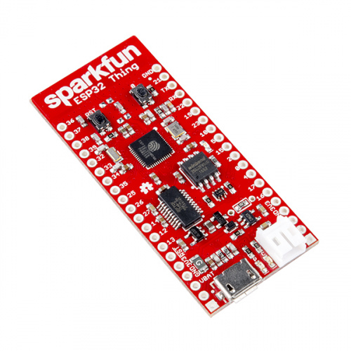
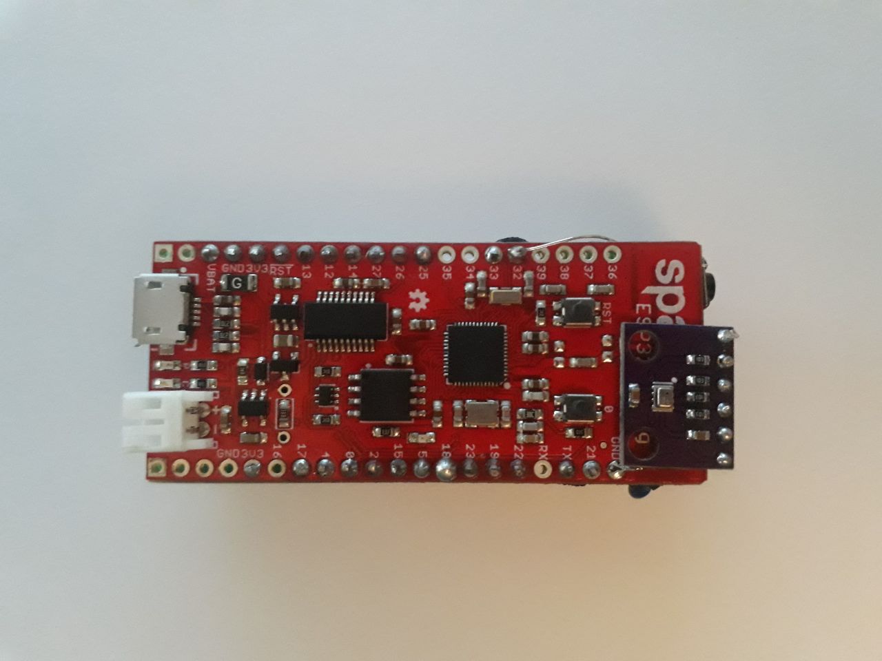
  • Placa ESP32-Thing de SparkFun
    >>Microcontrolador de altas prestaciones con conectividad WIFI y Bluetooth gracias al chip ESP32 integrado, ideal para proyectos de IoT.
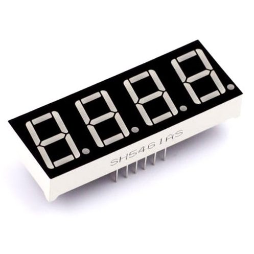
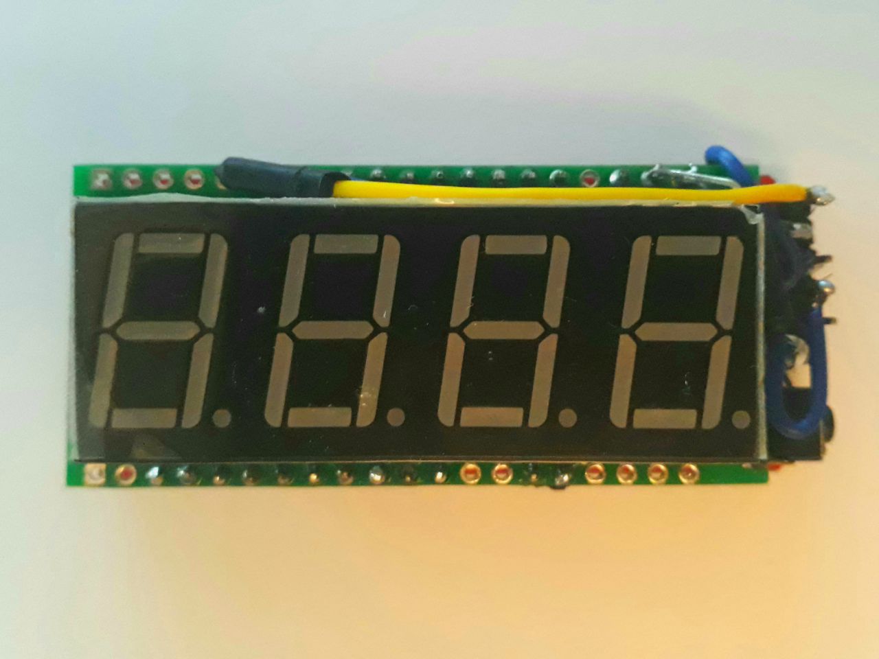
  • Pantalla de 4 dígitos de 7 segmentos de color rojo.
    >>Mostrará la hora y la temperatura.
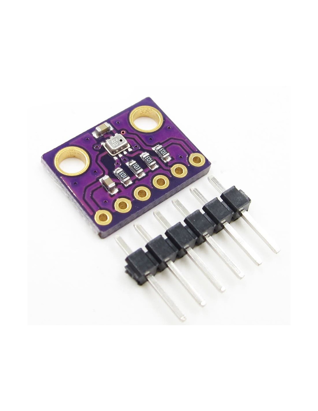
  • Módulo BMP-280
    >>Sensor digital de temperatura y presión barométrica muy compacto.
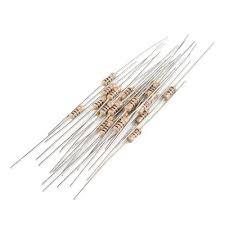
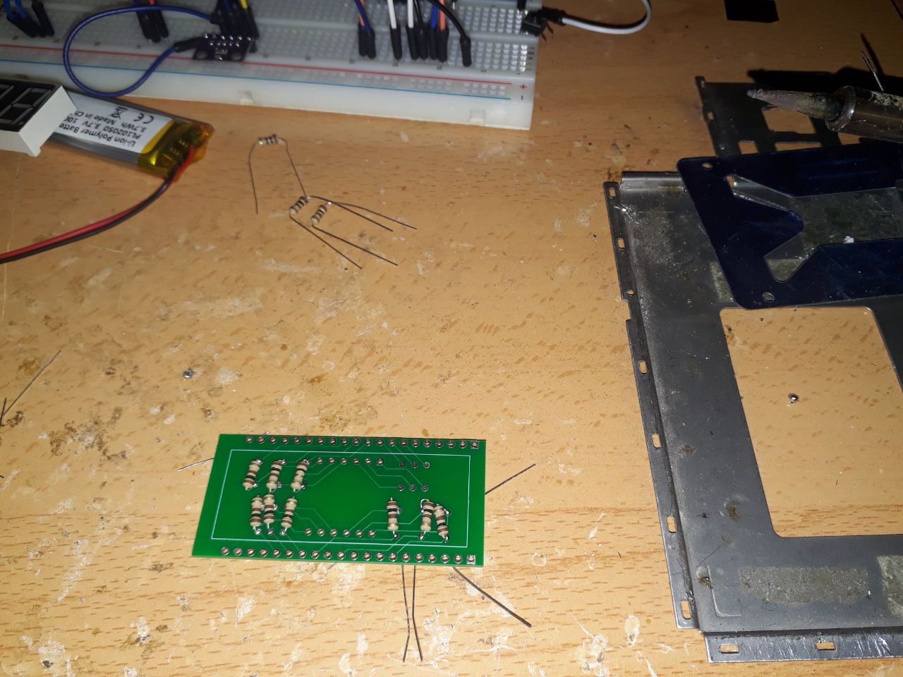
  • Resistencias de 100 Ohm.
    >>Necesarias para reducir la corriente en la pantalla, sin disminuir excesivamente su brillo (admite hasta 1k Ohm, pero así sería difícilmente visible con la luz del día).
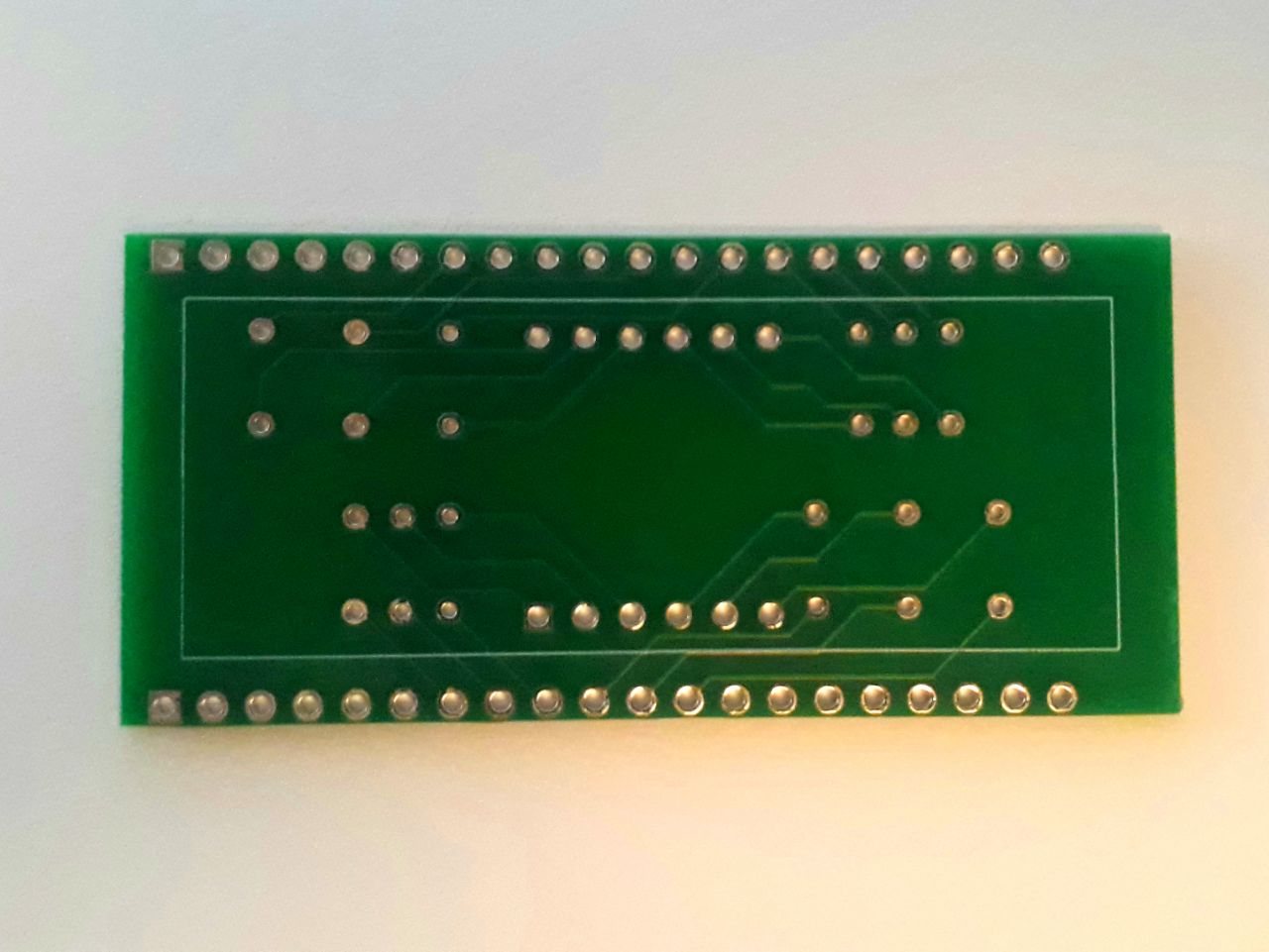
  • Placa PCB con circuito impreso personalizado.
    >>Simplifica la conexión de la pantalla y las resistencias al microcontrolador.
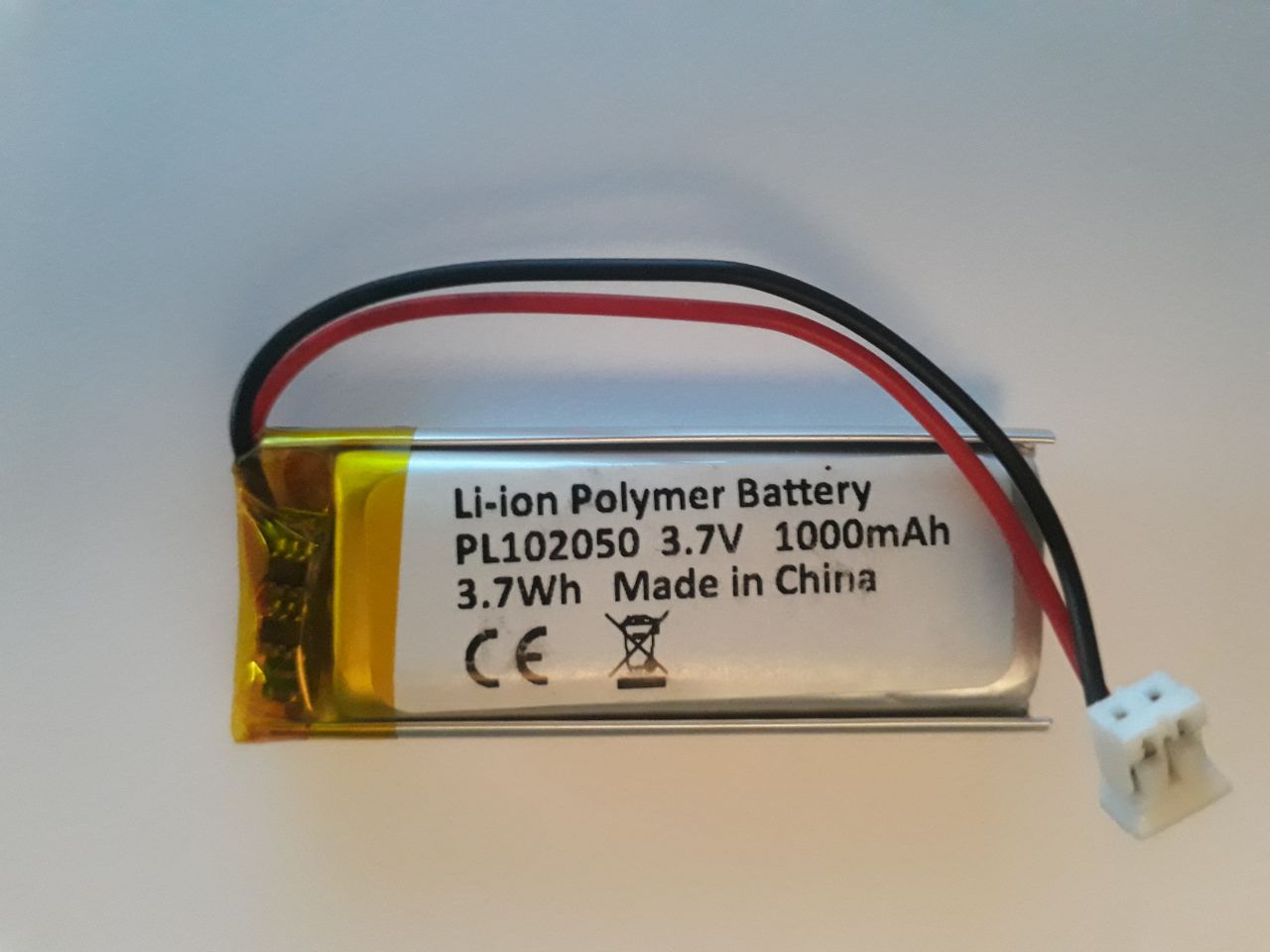
  • Batería LiPo 3.7v 1000mAh
    >>Asegura una autonomía de más de 48 horas sin alimentación externa.
  • Cables puente.
    >>Para realizar conexiones adicionales con los módulos externos.
  • Pulsador
    >>Usado para alternar el programa mostrado en pantalla.

Diseño electrónico

Es muy importante estudiar los componentes electrónicos que vamos a utilizar, leer todas las especificaciones y prototipar con todas las precauciones antes de ponernos a soldar como locos.

Elección de los componentes

Los componentes arriba listados no son mera casualidad ni copia de ninguna otra parte. Simplemente son la prueba más exitosa de muchas otras y que cumplen todas las necesidades del proyecto:

  • La pantalla de 4 dígitos muestra exclusivamente lo que busco ver: la hora. Si además puedo aprovechar para mostrar la temperatura, pues mejor. Pero una pantalla de más calidad, de tipo LCD, generaría un mayor consumo realmente innecesario ya que otra de las características fundamentales es la autonomía.
  • El microcontrolador cuenta con conexión a internet, así como suficiente capacidad de cómputo. Además, tiene suficientes pines entrada/salida para manejar la pantalla sin necesidad de un expansor de pines. Otras opciones que he probado:
    • Microcontroladores más compactos: Teensy 4, Digispark, SparkFun Pro Micro. Necesitan expansor de entrada/salida (PCF8574) y/o módulo WIFI (ESP-01). Además, requiere demasiadas conexiones.
    • Microcontralor con conexión WIFI integrada y suficientes E/S, como la NodeMCU con Esp8266. Faltaba potencia en el procesador y se retrasaba casi 4 segundos en cada minuto.

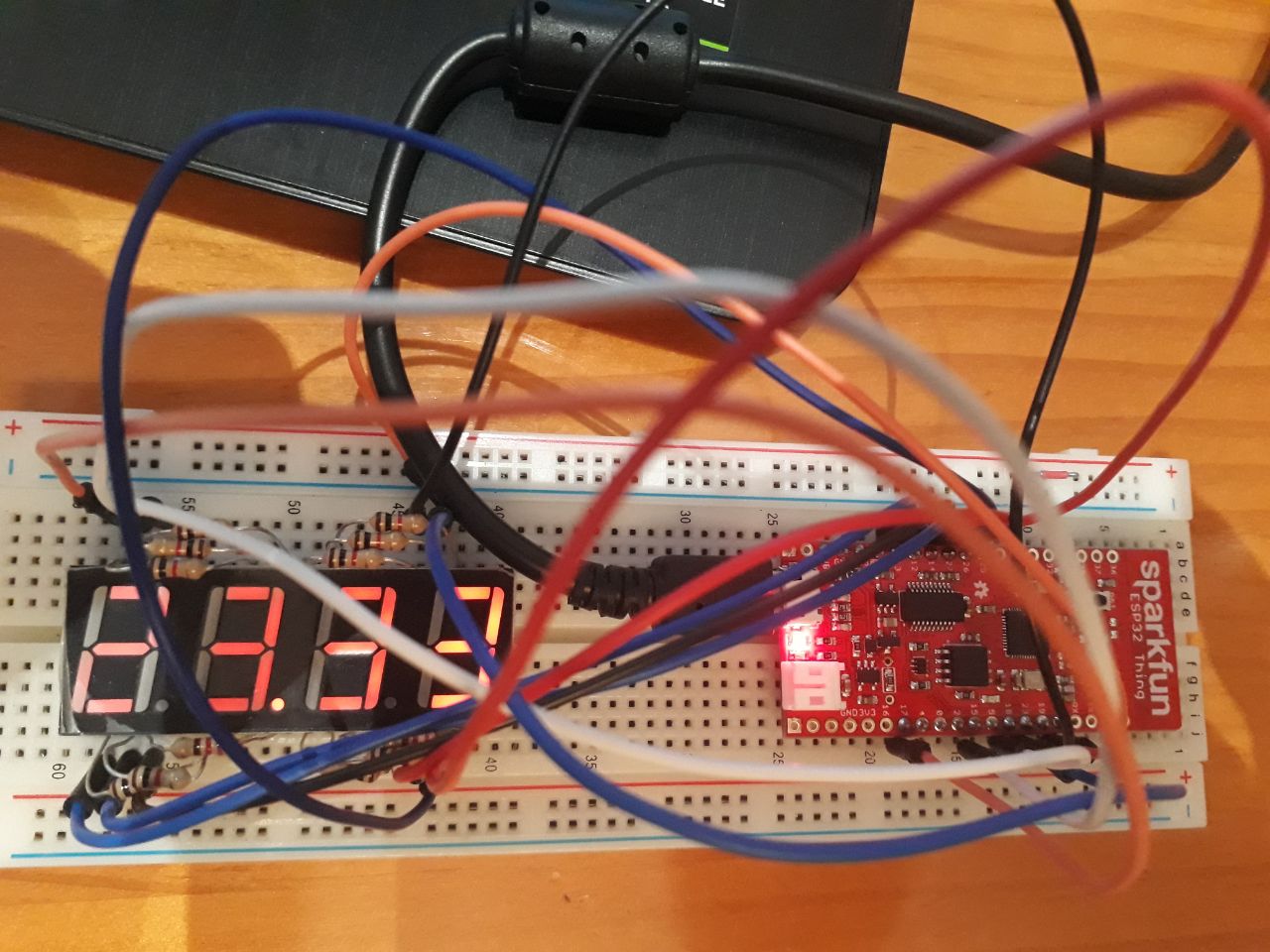
Prototipado del circuito eléctrico

Una vez estudiados y obtenidos los componentes, los conectamos en una placa de prototipos (o protoboard) para probar su funcionamiento.

En mi caso, tras varias combinaciones de pines, la forma más organizada me ha resultado ser la siguiente:

ESP32-ThingComponente
VBATLiPo +
3V3BMP-280 3V3
GNDLiPo -
BMP GND
BMP SD0
Pulsador -
GPIO21BMP SDA
GPIO04BMP SCL
GPIO32Pulsador +
GPIO17Pantalla Dígito 1
GPIO23Pantalla Dígito 2
GPIO19Pantalla Dígito 3
GPIO25Pantalla Dígito 4
GPIO15Pantalla Segmento A
GPIO22Pantalla Segmento B
GPIO27Pantalla Segmento C
GPIO12Pantalla Segmento D
GPIO13Pantalla Segmento E
GPIO18Pantalla Segmento F
GPIO26Pantalla Segmento G
GPIO14Pantalla Segmento P (punto)

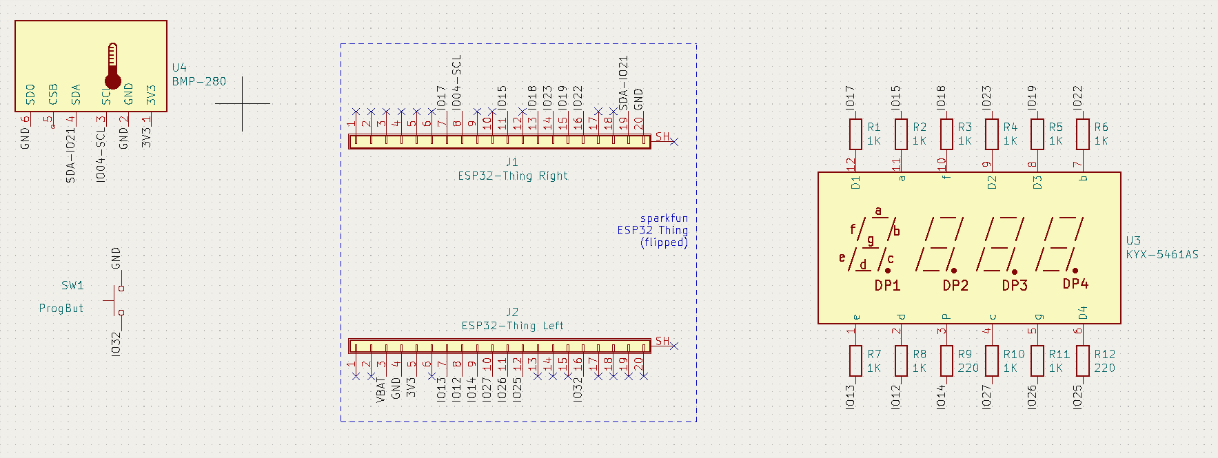
Esquema de patillaje

Una vez tengamos el prototipo montado, es bueno pasarlo a un esquema con un programa de EDA (automatización de diseño electrónico) como Kicad, donde también podremos generar un diseño de PCB para mandar a fabricar. Si no, siempre puedes hacer el esquema en papel, ya que dentro de dos meses no vas a recordar dónde iba cada cable...

Kicad tiene su truquillo y es bueno practicar antes con proyectos más sencillos. Aun así, es asequible para usuarios medios, ya que básicamente consiste en buscar y elegir símbolos de nuestros componentes y conectar sus pines correctamente según sus especificaciones.

Yo, para no liar la cosa de cables en el papel, he usado nombres en cada conexión, que también es válido en Kicad. Además, verás que la ESP32-Thing está compuesta por dos tiras de 20x pines, ya que no encontré ningún símbolo que me funcionara y no tenía tiempo de diseñarlo como toca. Lo importante es que nuestro diseño funcione y sea coherente con la realidad.

Esquema de Kicad

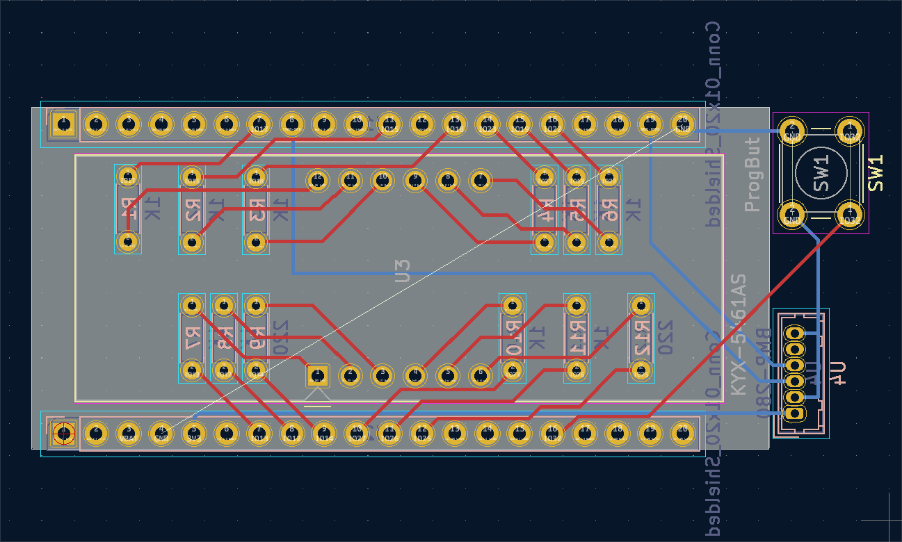
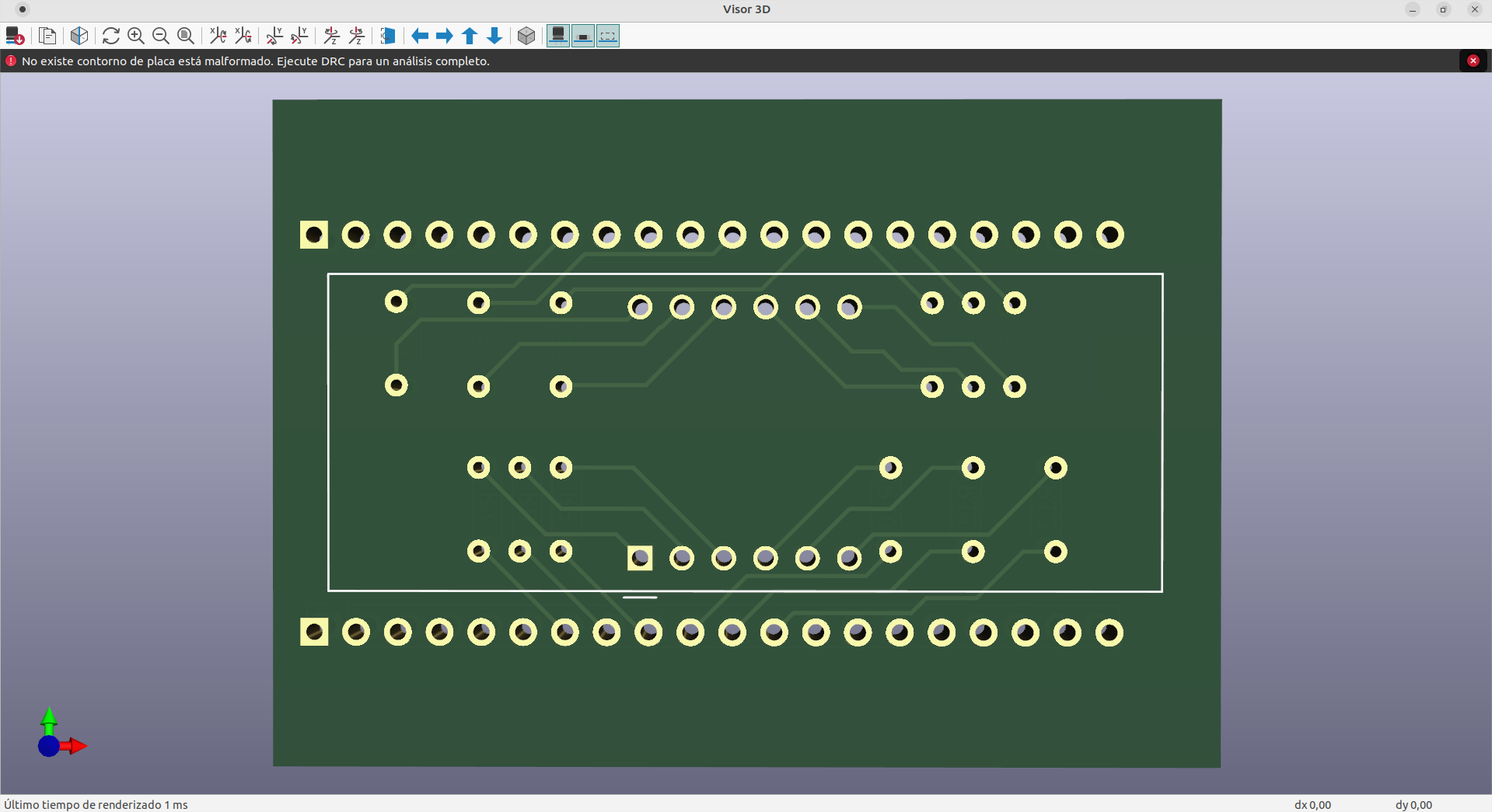
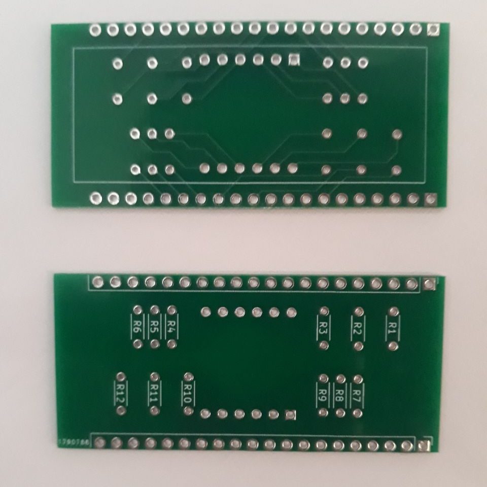
Lo siguiente es asignar huellas realistas (o footprints) a cada símbolo de componente, y entonces podremos diseñar una placa de circuito impreso (o PCB) que podemos enviar a fabricar (normalmente a China) por unos 15€ / 5 placas.

No hay que volverse muy locos con esto, especialmente si no somos expertos. Yo solo lo uso para facilitar las soldaduras cuando hay muchas conexiones, como es este caso donde se realizan unas 90 soldaduras pero se mantiene un formato bastante compacto.

Programación del reloj

La mayoría de microcontroladores, como el ESP32-Thing, son compatibles con el IDE de Arduino, lo cual facilitará la conexión con la placa para enviarle un programa de reloj.

Antes de empezar, es importante hacer un pequeño listado de las tareas y funciones que queremos incluir en el programa e irlo modificando mientras las programamos. De esta forma podremos probar las distintas funciones por separado, y debuguear los distintos pasos para corregir errores más rápidamente. En mi caso, de nuevo tras muchas pruebas, quiero que el programa conste de lo siguiente:

  1. Definición de librerías y variables.
  2. Configuración de pines.
  3. Conexión WiFi.
  4. Obtener fecha por SNTP.
  5. Desconexión y apagado de WiFi (ahorra batería).
  6. Conversión de fecha a dígitos.
  7. Muestra de dígitos en pantalla.
  8. Iniciar temporizador.
  9. Iniciar lectura de pin de cambio de programa.
  10. Cambio de programa al activar el pulsador.
    1. Lectura de sensores.
    2. Muestra de temperatura en pantalla.
  11. Actualizar hora al finalizar el temporizador (cada minuto).
  12. Reiniciar temporizador.

No me quiero entretener mucho con el código, y encima no es el más ordenado que tengo, pero lo dejo aquí incrustado para quien lo quiera copiar, o también en github:

https://github.com/TheRoam/Tempsi-7

//----------------------------------------------------------------//
//    Temps-i 7 WiFi clock and temperature in 4 digit display     //
//  v 1.0.1                                                       //
//                                                                //
//  Interfaces:                                                   //
//  - Sparkfun ESP32-Thing micocontroller                         //
//  - BMP-280 temperature and pressure digital sensor             //
//  - 4 digit 7 segment display                                   //
//  - Programm push button                                        //
//  - LiPo Battery                                                //
//                                                                //
//  Detailed documentation:                                       //
//  https://theroamingworkshop.cloud                              //
//                                                                //
//                © THE ROAMING WORKSHOP 2022                     //
//----------------------------------------------------------------//
#include < esp_wifi.h >
#include < WiFi.h >
#include < WiFiMulti.h >
#include "time.h"
#include "sntp.h"
#include < Wire.h >
#include < Adafruit_BMP280.h >
// Spaces inside <> only shown for correct html display. Remove them in Arduino IDE
//BMP280 sensor using I2C interface
Adafruit_BMP280 bmp;
#define BMP_SCK  (4)
#define BMP_MISO (21)
#define BMP_MOSI (4)
#define BMP_CS   (21)
//Sensor variables
float TEMP=0;     //temperature variable
float ALT=0;      //altitude variable
float PRES=0;     //pressure variable
float hREF=1020.0;//sea level reference pressure in hPa
//define time variables
RTC_DATA_ATTR long long TIME=0; //concatenated time
RTC_DATA_ATTR long long d=0;  //day
RTC_DATA_ATTR long long m=0;  //month
RTC_DATA_ATTR long long Y=0;  //year
RTC_DATA_ATTR long long H=0;  //hour
RTC_DATA_ATTR long long M=0;  //minute
RTC_DATA_ATTR long long S=0;  //second
RTC_DATA_ATTR uint32_t dS=0;  //seconds counter for dot
RTC_DATA_ATTR struct tm timeinfo; //saves full date variable
long long inicio=0; //saves start time
long long ahora=0;  //saves current time
//Define digit pins in an array, in display order, for looping
//Numbers match ESP32-Thing GPIO number
int DigPins[4]{
  17,// first digit (GPIO 17)
  23,//second digit (GPIO 23)
  19,//third digit  (GPIO 19)
  25//fourth digit  (GPIO  25)
};
//Define segment pins
//Numbers match ESP32-Thing GPIO number
int SegPins[8]{
  14,   //P
  26,   //g
  18,   //f
  13,   //e
  12,   //d
  27,   //c
  22,   //b
  15    //a
};
//Auxiliary variables
//Numbers match ESP32-Thing GPIO number
int ProgPin=32;   //Pin no used for program
int ButtonStatus=1;
int ledPin=5;     //Used to blink the ESP32-Thing blue led
int ProgNum=-1;   //Define a variable to keep track of current program number
// WIFI
// Define your wifi network and credentials
char ssid1[] = "YOUR_WIFI_SSID1";
char pass1[] = "YOUR_WIFI_PASS1";
char ssid1[] = "YOUR_WIFI_SSID2";
char pass1[] = "YOUR_WIFI_PASS2";
WiFiMulti wifiMulti;
// NTP variables
// Update time zone if needed
const char* ntpServer1 = "pool.ntp.org";
const char* ntpServer2 = "time.nist.gov";
const long  gmtOffset_sec = 3600;
const int   daylightOffset_sec = 0; //this will be corrected later with software
const char* time_zone = "CET-1CEST,M3.5.0,M10.5.0/3";  // TimeZone rule for Europe/Rome including daylight adjustment rules (optional)
// Displayed characters in every digit are a byte array indicating ON (1) and OFF (0) segments
// Use a wiring pattern that matches an understandable byte chain so you can make them up easily
// Segment/byte pattern: Babcdefgp --> where 1 is HIGH (ON) and 0 is LOW (OFF)
// Refer to a character by calling this array, i.e.:
//  - call number 3 by calling ns[3]
//  - call letter A by calling ns[20]
//  - call underscore symbol (_) by calling ns[49]
byte ns[50]{ // Array Position - Byte character
  B11111100,// 0-0
  B01100000,// 1-1
  B11011010,// 2-2
  B11110010,// 3-3
  B01100110,// 4-4
  B10110110,// 5-5
  B10111110,// 6-6
  B11100000,// 7-7
  B11111110,// 8-8
  B11110110,// 9-9
  B11111101,// 10-0.
  B01100001,// 11-1.
  B11011011,// 12-2.
  B11110011,// 13-3.
  B01100111,// 14-4.
  B10110111,// 15-5.
  B10111111,// 16-6.
  B11100001,// 17-7.
  B11111111,// 18-8.
  B11110111,// 19-9.
  B11101110,// 20-A
  B00111110,// 21-b
  B10011100,// 22-C
  B01111010,// 23-d
  B10011110,// 24-e
  B10001110,// 25-f
  B10111100,// 26-G
  B00101110,// 27-h
  B00001100,// 28-I
  B11111000,// 29-J
  B01101110,// 30-K(H)
  B00011100,// 31-L
  B00101010,// 32-m(n)
  B00101010,// 33-n
  B00111010,// 34-o
  B11001110,// 35-P
  B11100110,// 36-q
  B00001010,// 37-r
  B10110110,// 38-S
  B00011110,// 39-t
  B01111100,// 40-U
  B00111000,// 41-v
  B00111000,// 42-w(v)
  B01101110,// 43-X(H)
  B01110110,// 44-y
  B11011010,// 45-Z
  B00000001,// 46-. (dot)
  B11000110,// 47-* (astherisc)
  B00000010,// 48-- (hyphon)
  B00010000,// 49-_ (underscore)
};
//array to store displayed digits
int digits[4];
//digit calculation variables
int first_digit = 0;
int second_digit = 0;
int third_digit = 0;
int fourth_digit = 0;
//counters for looping digits and current number
int dig=0;
int n=0;
int dot=1;
void setup()
{
  // Start disabling bluetooth and WIFI to save energy
  // Just power WIFI later, when needed.
  esp_err_t esp_bluedroid_disable(void);
  esp_err_t esp_bt_controller_disable(void);
  WiFi.disconnect(true);
  WiFi.mode(WIFI_OFF);
  
  // Start serial communication for any debug messages
  // Commented for production; uncomment for debugging
  //Serial.begin(115200);
  //Define I2C pins, as we are not using standard ones
  Wire.begin(21,4);
  // Activate digit pins looping the pin array.
  for (dig=0; dig<4; dig++){
    pinMode(DigPins[dig], OUTPUT);
  }
  for (dig=0; dig<4; dig++){  //set them LOW (turn them OFF)
    digitalWrite(DigPins[dig], LOW);
  }
  // Activate segment pins
  for (int i=0; i<8; i++){
    pinMode(SegPins[i],OUTPUT);
  }
  // Activate LED pin
  pinMode(ledPin, OUTPUT);
  // Activate PROG pin
  pinMode(ProgPin, INPUT_PULLUP);
  // Turn ON Wifi
  wifiON();
  
  // Setup NTP parameters
  sntp_set_time_sync_notification_cb( timeavailable );
  sntp_servermode_dhcp(1);
  configTime(gmtOffset_sec, daylightOffset_sec, ntpServer1, ntpServer2);
  //wait for date
  do{
    delay(100);
  }while(TIME==0);
  delay(500);
  //WIFI can be turned off now
  wifiOFF();  
  // Setup BMP280
  unsigned status;
  //BMP-280 I2C Address:
  // 0x76 if SD0 is grounded
  // 0x77 if SD0 is high
  status = bmp.begin(0x76);
  if (!status) {
    Serial.println(F("Could not find a valid BMP280 sensor, check wiring or "
                      "try a different address!"));
    Serial.print("SensorID was: 0x"); Serial.println(bmp.sensorID(),16);
    Serial.print("        ID of 0xFF probably means a bad address, a BMP 180 or BMP 085\n");
    Serial.print("   ID of 0x56-0x58 represents a BMP 280,\n");
    Serial.print("        ID of 0x60 represents a BME 280.\n");
    Serial.print("        ID of 0x61 represents a BME 680.\n");
    ESP.restart();
    while (1) delay(10);
  }
  //Default settings from datasheet.
  bmp.setSampling(Adafruit_BMP280::MODE_NORMAL,     // Operating Mode.
                  Adafruit_BMP280::SAMPLING_X2,     // Temp. oversampling
                  Adafruit_BMP280::SAMPLING_X16,    // Pressure oversampling
                  Adafruit_BMP280::FILTER_X16,      // Filtering.
                  Adafruit_BMP280::STANDBY_MS_500); // Standby time.
  //get initial readings
  readSensors();
  
  // Get correct time
  sync_clock();
  num_shift();
  // Set start time
  inicio = millis();
  // Set dot time
  dS=millis();
}
void loop(){
  // After setup, this function will loop until shutdown.
  
  // Start time counter using chip's milisecond counter
  uint32_t ahora=millis();
  
  // Check if the counter has reached 60000 miliseconds.
  // Calibrate if you realize that time desyncs
  // This depends on processor calculation, which can vary with input voltage (if on batteries) and temperature.
  while ( (ahora-inicio+(S*1000)) < 59500){
    // Run dot blinker when not showing temperature
    //commented as it sometimes desyncs the hour digit (needs fixing)
    /*if(ProgNum==-1){
      dot_blinker();
    }*/
    
    // Reading push button:
    // when pressed change status
    if(digitalRead(ProgPin)==1){
      ButtonStatus=1;
    }
    // when released after press, set "program change" status
    // this avoids constant change when holding
    if(digitalRead(ProgPin)==0 && ButtonStatus==1){
      ButtonStatus=2;
    }
    // Status 2 -> Programm change
    if(ButtonStatus==2){
      //reset status
      ButtonStatus=0;
      //update programm number
      ProgNum=-ProgNum;
      Serial.println(ProgNum);
      //change to temp
      if(ProgNum==1){
       //light LED
       digitalWrite(ledPin, HIGH); 
       //save TIME
       TIME=digits[0]*1000+(digits[1]-10)*100+digits[2]*10+digits[3];
       //show temp
       room_temp();
      }else if(ProgNum==-1){  //change to time
        //turn off LED
        digitalWrite(ledPin, LOW);
        //restore time
        split_time(TIME);
      }
    }
    
    //update time counter
    ahora=millis();
    num_shift();
    delay(6);
  }
  // End of while() after 60 seconds
  // Reset initial time
  S=0;
  inicio=millis();
  //make sure there's dot at the end
  if(digits[1]<=10){
    digits[1]+10;
    dot=0;
  }
  //update time
  //if program is in temperature, change to time
  if(ProgNum==1){
    split_time(TIME);
    ProgNum=-1;
  }
  updateMinutes();
}
//-WIFI function
//--Setup and turn Wifi ON
void wifiON(){
  // Set up WIFI (ESP32 Thing only working with wifiMulti library)
  Serial.println("Conectando");
  wifiMulti.addAP(ssid1,pass1);
  //wifiMulti.addAP(ssid2,pass2);
  int led=1;
  int boot=1;
  wifiMulti.run();
  //WiFi.disconnect(true);
  
  while((WiFi.status() != WL_CONNECTED)){
    digitalWrite(ledPin, HIGH);
    delay(500);
    digitalWrite(ledPin,LOW);
    delay(500);
    wifiMulti.run();
  }
  // Make sure LED is off when finished
  digitalWrite(ledPin,LOW);
  // When CONNECTED, while loop ends.
  Serial.print("Conectado a ");
  Serial.println(WiFi.SSID());
  Serial.println(WiFi.localIP());
}
//-Disable WIFI
void wifiOFF(){
  //turn WIFI off as it's not needed any more
  WiFi.disconnect(true);
  WiFi.mode(WIFI_OFF);
  //disable wifi (deinit clears all flash data)
  esp_wifi_deinit();
}
//----BMP280 functions
//-Read sensor data
void readSensors(){
  TEMP=bmp.readTemperature();
  Serial.println("T: "+(String)TEMP+"ºC");
  PRES=bmp.readPressure();
  Serial.println("P: "+(String)PRES+"hPa");
  ALT=bmp.readAltitude(hREF);
  Serial.println("h: "+(String)ALT+"msnm");
}
//----NTP functions
//-Callback function (get's called when time adjusts via NTP)
void timeavailable(struct timeval *t)
{
  Serial.println("Got time adjustment from NTP!");
  simpleTime();
}
void simpleTime()
{ 
  if(!getLocalTime(&timeinfo)){
    Serial.println("No time available (yet)");
    return;
  }
  Serial.print("Synced time: ");
  Serial.println(&timeinfo, "%A, %B %d %Y %H:%M:%S");
  //save time
  sync_clock();
}
//-
//PROGRAM #0: HELLO at startup
//function to say "HOLA" at start up while connecting to WiFi
void ini_HOLA(){
  int h=30;
  int o=34;
  int l=31;
  int a=20;
  digits[0]=46;
  digits[1]=46;
  digits[2]=46;
  digits[3]=46;
}
//PROGRAM #1: WiFi synced time
//function that gets current time via WiFi
void sync_clock(){
  Y=timeinfo.tm_year;
    TIME=TIME+Y*10000000000;
  m=timeinfo.tm_mon;
  m=m+1;
    TIME=TIME+m*100000000;
  d=timeinfo.tm_mday;
    TIME=d*1000000;
  H=timeinfo.tm_hour;
  //check daylight saving time and correct hour
  //"27 Mar (03 27) +1 hour; 30 Oct (10 30) back -1 hour"
  if( ( m*100+d >= 327 ) && ( m*100+d < 1030 ) ){
    H=H+1;
  }else{
    H=H;
  }
  TIME=TIME+H*10000;
  M=timeinfo.tm_min;
    TIME=TIME+M*100;
  S=timeinfo.tm_sec;
    TIME=TIME+S;
    
  //split current 4 digit time into sigle digits
  split_time((TIME/100)-((TIME/100)/10000)*10000);
}
//number splitting function to separate time string into digits
void split_time(long long num) {
  first_digit = num / 1000;
  digits[0] = first_digit;
  int first_left = num - (first_digit * 1000);
  second_digit = first_left / 100;
  digits[1] = second_digit;
  //añadimos el segundero fijo (sumamos 10)
  digits[1] = digits[1]+10;
  int second_left = first_left - (second_digit * 100);
  third_digit = second_left / 10;
  digits[2] = third_digit;
  fourth_digit = second_left - (third_digit * 10);
  digits[3] = fourth_digit;
}
// number shifting function
void num_shift(){
  for (dig=0; dig<4; dig++){// turn digits off
    digitalWrite(DigPins[dig], HIGH);
  }
  
  //turn them ON (LOW) one by one
    digitalWrite(DigPins[n], LOW);
    for(int seg=7; seg>=0; seg--){
      //read byte array for digit
      int x = bitRead(ns[digits[n]],seg);
      //turn the segments ON or OFF
      digitalWrite(SegPins[seg],x);
    }
    n++;// move to next no.
    if (n==4){// if no. is 4, restart
      n=0;
    }
}
//Getting room temperature from LM35 sensor via NodeMCU analog input pin (ADC)
void room_temp(){
  readSensors();
  //This will return temperature in XY.Z format
  //We don't want the integer value, so we can use the four digits to display temperature units as well "XYºC"
  //Getting first digit in byte format ns[X] where X=int(XY.Z/10)=int(X.YZ)=X
  digits[0]=int(TEMP/10)-int(TEMP/100)*10;
  //Getting second digit in byte format ns[Y] where Y=int(XY.Z)-X*10=int(XY.Z)-int(XY.Z/10)*10
  digits[1]=int(TEMP/1)-int(TEMP/10)*10;
  //Setting temperature units as degree celsius (ºC) in byte format
  digits[2]=47; //astherisc *
  digits[3]=22; //character C
}
void updateMinutes(){
  //add 1 to the last digit
  digits[3]=digits[3]+1;
  //if greater than 9, reset to 0
  if (digits[3]>9){
    digits[3]=0;
    //then add 1 to the third digit
    updateM0();
  }
  //send last digit to display
  digitalWrite(DigPins[3], LOW);
}
void updateM0(){
  //add 1 to third digit
  digits[2]=digits[2]+1;
  //if greater than 5, reset to 0
  if (digits[2]>5){
    digits[2]=0;
    //then add 1 to current hours
    updateH1();
  }
  //send digit to display
  digitalWrite(DigPins[2], LOW);
}
void updateH1(){
  //add 1 hour
  digits[1]=digits[1]+1;
  // if greater than 19, reset to 10
  // (instead of number 0-9, we use numbers 10-19 in order to add the "dot" to the display)
  if (digits[1]>19){
    digits[1]=10;
    //then add 1 to the first digit
    updateH0();
  }// reset when it's 24h (go back to 00)
  if(digits[1]>13 && digits[0]==2){
    digits[0]=0;
    digits[1]=10;
  }
  //display digits
  digitalWrite(DigPins[1], LOW);
  digitalWrite(DigPins[0], LOW);
}
void updateH0(){
  //add 1 to first digit
  digits[0]=digits[0]+1;
  //if greater than 2, reset to 0 (it shouldn't happen as we reset earlier, but just in case..)
  if (digits[0]>2){
    digits[0]=0;
  }
  //display digit
  digitalWrite(DigPins[0], LOW);
}
void dot_blinker(){
  //every second, blink the dot
    if( millis()-dS > 1000 && dot == 1){
      digits[1]=digits[1]-10;
      dS=millis();
      dot=0;
    }
    if( millis()-dS > 250 && dot == 0){
      digits[1]=digits[1]+10;
      dot=1;
    }
}

Ten en cuenta que se hace uso de las siguientes librerías adicionales que deberás instalar usando el IDE de Arduino:

  • Gestor de placas esp32 de Espressif
  • Librería WiFiMulti
  • Librería Adafruit_BMP280
    • (el resto de librerías se derivan de las anteriores)

Deberemos probar constantemente el funcionamiento del código durante la fase de prototipado para poder cambiar la asignación de pines en caso de algún mal funcionamiento. Si ya está todo soldado y nos falla algo, será bastante más complicado encontrar y resolver el error, de ser en alguna conexión.

Ensamblaje

Soldaduras

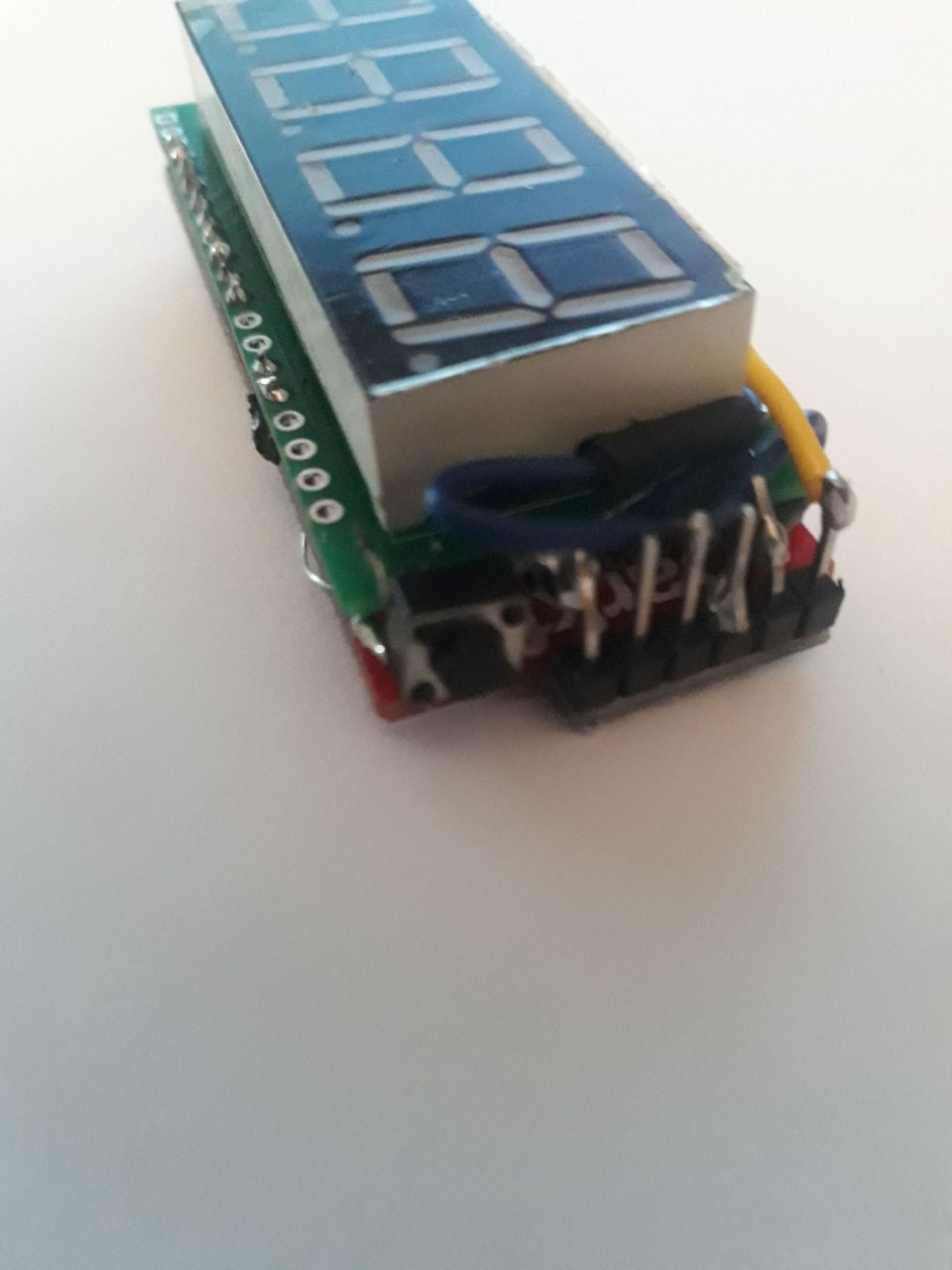
Una vez comprobado el código y diseñada la PCB, ya podemos empezar a soldar, teniendo claro donde va cada cosa y tomando mucha precaución, porque una mala soldadura puede arruinarte cualquier módulo o generar errores en el programa.

Diseño de carcasa

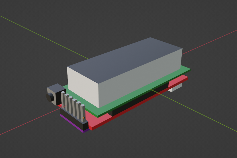
Con todo soldado y montado ya tenemos una mejor idea del volumen real del dispositivo. Yo lo voy a medir todo milimétricamente con un pie de rey para hacer un modelo 3D de la placa ya montada.

Modelo 3D en Blender de los componentes conectados en su posición final

Así puedes diseñar una carcasa alrededor del modelo y fabricarla con una impresora 3D, pero puedes buscar otros tipos de ensamblajes con madera o metal laminados.

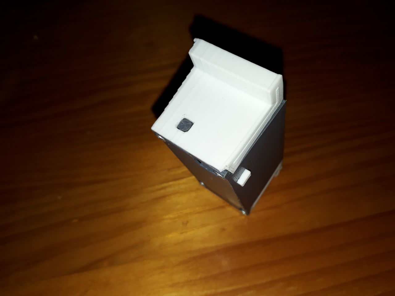
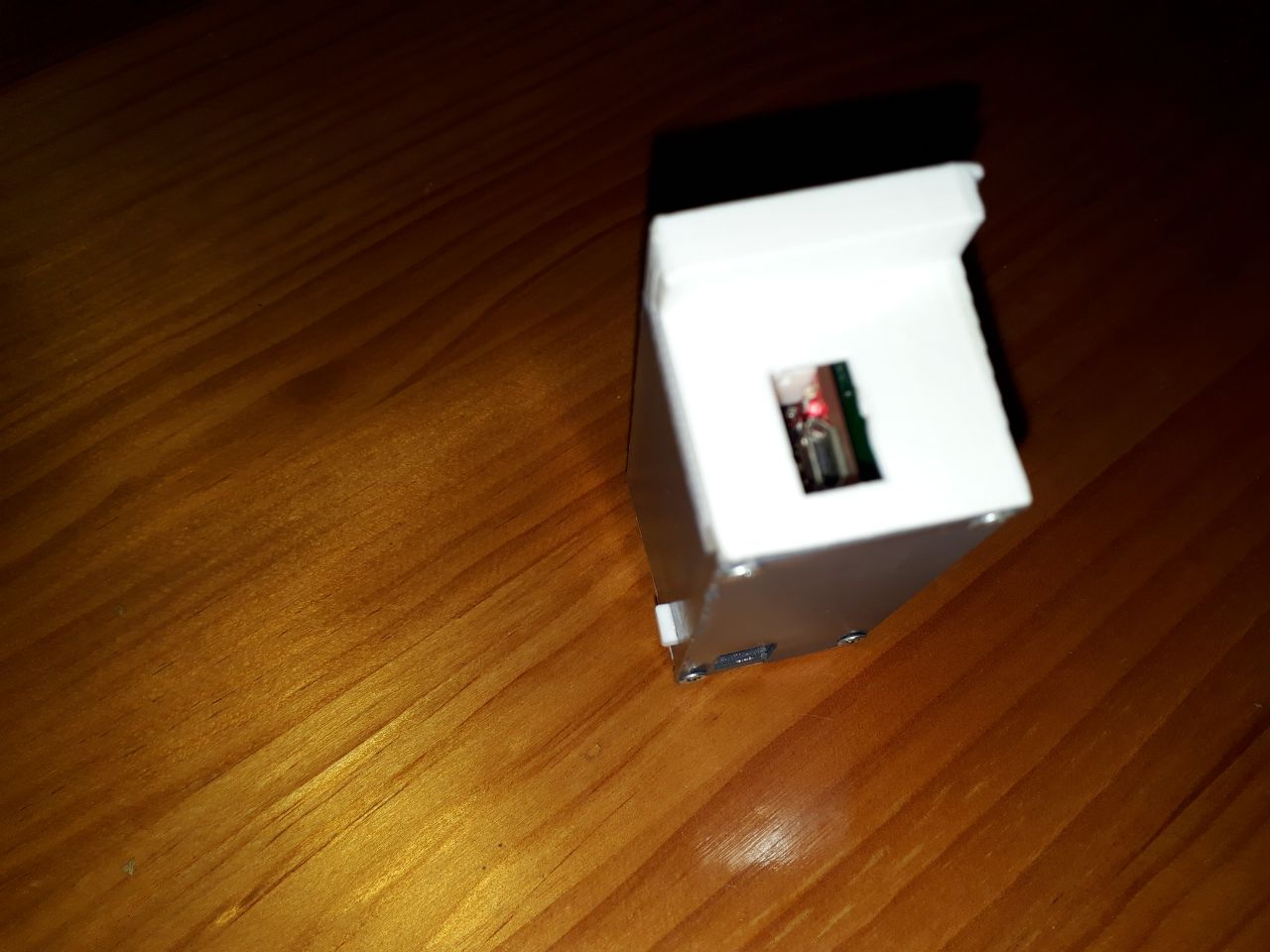
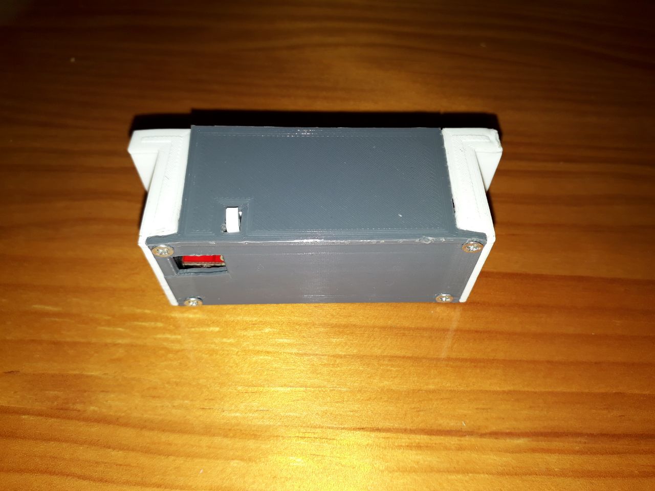
Yo suelo usar dos piezas (una de base y otra de tapa) para poder atornillar la una a la otra. También voy a incluir distintos huecos para permitir la conexión del cable USB, para añadir el pulsador de cambio de programa y para añadir un soporte rotatorio que encajará el reloj en una ranura del televisor.

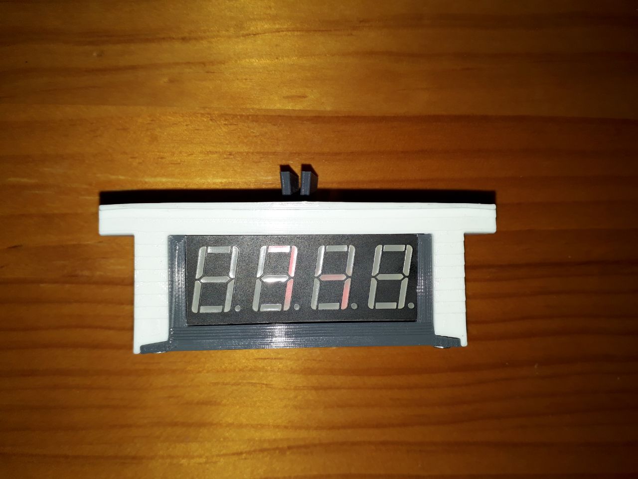
Además usaré PLA blanco en una pieza y gris en otra para darle algo más de vida al diseño, quedando todo así:

Y eso es todo. Espero que te haya gustado y te sea útil. ¡Lánzate a montar tu propio reloj WIFI! Cualquier duda sobre este reloj, al Twitter! 🐦

🐦 @RoamingWorkshop